 メインコンテンツへスキップ フッターへスキップ
スティック掃除機メーカーは、80 cm³未満のモーター容積に300Wから600Wの電力を詰め込むという、ますます大きな課題に直面しています。これらの高速ブラシレスモーターは激しい廃熱を発生させ、適切に管理しないと、高感度な電子部品を損傷させたり、安全温度限界を超えたりする可能性があります。効果的なスティック掃除機の熱管理には、電力密度、冷却空気流、材料耐久性の間の精密なバランスが必要であり、コンパクトなハンドヘルド筐体内での過熱を防ぎます。.
本ガイドでは、空気流冷却経路から熱遮断(TCO)スイッチの統合まで、熱安全性の技術的構成要素を解説します。モーター温度を80°C未満に保つための高伝導性A356アルミニウム合金の使用を分析し、毎秒20メートルの最小空気速度の維持が、ゴミの輸送とモーター冷却の両方を確実にする方法を検証します。また、IEC/UL 60335-2-2安全規格への適合を確認するための「ホース閉塞」テストなどの試験プロトコルもレビューします。.
狭い空間における高出力の課題
現代のスティック掃除機は、80 cm³未満のモーター容積に300Wから600Wの電力を詰め込み、極端な電力密度を生み出しています。毎分100,000回転を超える高速ブラシレスモーターは激しい廃熱を発生させ、安全温度限界を超えたり内部電子部品を損傷させたりしないよう、薄いプラスチック筐体を通じて管理する必要があります。.
コンパクト筐体における電力密度と熱流束
2026年のコードレスモーターは300Wから500Wを消費し、ハイエンドモデルでは600W以上の電気入力を超えます。このエネルギーは80 cm³未満のモーター容積内で変換され、そのモーターは重量3kg未満のハンドヘルドユニット内に収まっています。結果として生じる電力密度は従来のコード付き家電製品を大幅に上回り、狭い物理的設置面積に熱エネルギーを集中させます。.
毎分80,000から100,000回転で動作するブラシレスDCモーターは、激しい熱を発生するローター損傷と巻線損傷を生み出します。軽量なプラスチック筐体は対流冷却のための表面積が限られているため、コアから熱を拡散させることが困難です。エンジニアは最小限の金属構造を使用してこの廃熱を伝導しながら、掃除機の外装をユーザーにとって快適な温度に保ちます。.
内部コンポーネントは、工業用恒温槽で見られるような状態を再現する局所的なホットスポットに耐える必要があります。これらの温度勾配は、しばしば-50°Cから+250°Cの範囲に及びます。これらの極限状態を管理するには、高性能の断熱材と特殊な空気流経路が必要であり、高感度な電子部品とバッテリーパックを熱劣化から保護します。.
規制適合性と安全性能の限界
IEC/UL 60335-2-2規格は、火災の危険とユーザーの傷害を防ぐため、表面温度と絶縁クラスに厳しい制限を設けています。これらの規則により、高出力設定での長時間使用中でも、掃除機が安全に触れることができる状態を保証します。設計者は、積極的な性能目標と、これらの安全上義務付けられた熱的マージンのバランスを取る必要があります。.
ASTM F2105-21は、空気性能の具体的な測定を義務付け、入力電力を温度上昇に直接関連付けます。これにより、メーカーが熱問題を隠すために人為的に性能を低下させることを防ぎます。この規格は、異なる動作条件にわたって空気性能曲線が正確であることを要求し、熱管理を中核的な設計要件としています。.
ASTM F1977-22に基づく試験では、フィルターの圧力損失とダスト負荷がモーターへの負荷を増加させることが示されています。フィルターが目詰まりすると、モーターは吸引力を維持するためにより多くの電流を消費し、内部温度が上昇します。設計者は、冷却気流が著しく制限される「ホース詰まり」シナリオでも、システムが安全マージンを維持し、モーターが早期に熱的トリップポイントに達しないようにする必要があります。.
空気流冷却経路:通気口とダクトの設計
エンジニアは、モーターとバッテリーの温度を調整するために、バイパス方式またはフロースルー方式のいずれかを使用して気流経路を設計します。2026年までに、モーター排気をバッテリーパックに導くことが、性能を30%向上させる標準的な方法となっています。20 m/秒以上の風速を維持することで、安定した吸引力を確保し、内部ダクト内のダスト蓄積を防ぎます。.
| パフォーマンス指標 | 技術基準 | 工学的影響 |
|---|---|---|
| 吸引ホース速度 | ≥20 m/秒 | ダスト輸送と自己洗浄を保証(DS/EN 60335-2-69) |
| フィルター表面負荷 | ≤200 m³/h/㎡ | 過度の抵抗とモーターの過熱を防止 |
| バッテリー熱利得 | 30%の性能向上 | 使用中にモーター排気をバッテリーセル冷却へ導きます |
| システム吸水高 | 90インチ以上 | 〜からの抵抗に打ち勝ちます 7. HEPAフィルター、 および延長ホース |
モーター冷却構成:バイパス方式 vs. フロースルー方式
バイパス冷却は、独立したファンを使用してクリーンな室内空気をモーターアーマチュア周囲に循環させます。この分離により、モーターが湿った空気や汚れた吸入空気に接触するのを防ぎます。これはアップライト型、業務用タンク型、ウェット/ドライ掃除機に不可欠です。フロースルー方式は、濾過された吸入空気をモーター部品に直接通すため、家庭用スティック型およびキャニスター型モデルでより静かな動作プロファイルを実現します。エンジニアはフロースルー設計に安全サーモバルブを組み込み、一次吸引経路が塞がれた場合のフェイルセーフとして機能させ、冷却空気を供給するために開弁させます。.
モーター排気をバッテリーパックへ導く戦略的ダクト配線により、使用効率と稼働時間が30%向上します。この方法はコードレス型の熱負荷を管理します スティック掃除機 排気空気を利用してバッテリーセルからの熱を放散します。密閉型システムはこの気流の焦点をクリーニングヘッドに維持し、ゴミ除去に利用可能な毎分立方フィート(CFM)を最大化します。.
気速基準と圧力要件
吸引ホースは、粉塵輸送に関するDS/EN 60335-2-69規格に準拠するため、毎秒20メートルの最低気速を維持する必要があります。この特定の速度により、内部ダクトが破片で詰まらず、粒子がシステム内に沈着するのを防ぎます。例えば、直径40mmのホースに毎時150m³の空気を流すと、毎秒33メートルの速度が生成され、自己清掃の安全要件を上回ります。.
フィルター表面積は、システムへの負担を避けるため、1m²あたり毎時200m³の空気負荷に制限する必要があります。フィルターでの高抵抗によりモーターはより多くの電流を引き込み、冷却経路が塞がれている場合は過熱の可能性があります。ディープクリーニングの設計ベンチマークでは、通常、キャニスター型掃除機で100 CFM、アップライト型モデルで60 CFMが必要です。90インチの吸水高定格により、高密度HEPAフィルターや長い付属品を通して空気を引き込みながら、掃除機がこれらの気流レベルを維持できることがさらに保証されます。.
モーター熱遮断(TCO)安全スイッチ
サーマルカットオフ(TCO)スイッチは、温度が危険レベル(通常65°C〜180°C)に達したときに電気回路を遮断することで、掃除機モーターを保護します。システムは、一般的な過負荷に対するリセッタブルなバイメタルプロテクターと、重大な過熱に対する最終的な安全装置としての非リセッタブルなサーマルヒューズの両方を利用します。.
| コンポーネントカテゴリ | 技術仕様 | 安全機能 |
|---|---|---|
| バイメタルサーマルプロテクター | 60~180°C; 1~15A @ 250V AC | 復帰型保護; 過負荷時に開路し、冷却後に復帰します。. |
| One-Shot Thermal Fuse | 定格動作温度は最大954°C | 恒久的な回路遮断; 重要なフェイルセーフとして機能します。. |
| 真空システムの制限 | 120–150°C トリップポイント | ハウジングの変形を防ぎ、UL 2111 / EN 60730 準拠を保証します。. |
バイメタル式サーマルプロテクターとワンショットヒューズ
バイメタル式サーマルプロテクターは、一時的な過熱時に電気回路を遮断するリセッタブルスイッチとして機能します。これらの部品は、モーターが安全な差動温度、通常は30±15°Cまで冷えると自動的に閉じ、アプライアンスの動作を再開させます。ワンショットサーマルヒューズは、モーターが定格動作温度を超えたときに内部合金を溶融させて電流を永久に遮断することにより、恒久的な安全層を提供します。このリセット不可能なメカニズムは、壊滅的な故障が発生した場合の火災の危険を防ぎます。.
エンジニアはこれらの部品をモーターの巻線またはハウジングに直接組み込み、高負荷時やローター固着時の銅温度上昇を監視します。HCETなどのメーカーは、250V ACで1~15Aの定格の過負荷プロテクターを製造しており、これは特定の コードレスおよびコード付きスティック型掃除機の電力要件に モーターに適合します。センサーをモーターコイルの直接の熱経路に配置することで、システムは電流スパイクやエアフローの詰まりに迅速に反応します。.
動作しきい値と規制準拠
掃除機用途の標準的なTCOスイッチング温度は60°Cから180°Cの範囲で、正確な作動を保証するために通常±5°Cの許容差があります。スティック型掃除機システムは、多くの場合TCOトリップポイントを120~150°Cの範囲に設定して、プラスチックハウジングの変形を防ぎ、フィルター詰まり時のタッチ温度の安全性を維持します。このキャリブレーションにより、内部熱がモーター巻線の絶縁クラス限界を超える前にデバイスがシャットダウンすることが保証されます。.
UL 2111およびEN 60730規格への準拠は、これらの温度制御装置が家庭用電化製品に対する厳格な耐久性および誘電強度要件を満たしていることを検証します。Calco ASRシリーズなどの部品は250V / 10Aの定格を提供し、高吸引力のブラシレスモーターに見られるピーク電流を処理するために必要な容量を提供します。これらの規制枠組みへの準拠は、吸気口が完全に塞がれた状態やブラシロールが固着した状態などの異常な動作条件でも、掃除機が安全であることを保証します。.
カスタム高性能掃除機でブランドを拡大する

モーターハウジング用耐熱材料
エンジニアは、A356アルミニウム合金や熱安定化エンジニアリングプラスチックなど、熱伝導率と機械的強度が高い材料を優先します。これらの材料は、内部動作温度を120°C未満に保ち、絶縁破壊を防ぎ、コンパクトな 掃除機設計における高吸引力サイクル中の構造的完全性を確保します。.
高伝導性合金と軽量ポリマー
A356やAlSi10Mgなどのアルミニウム合金は、170 W/m·Kに達する熱伝導率を提供します。この効率性により、集中的な動作中でもモーター温度を80°C未満に維持できます。A356は、密度2.7 g/cm³、引張強度200~300 MPaを備え、高速ローター用の堅牢なフレームを提供します。耐衝撃性が優先される用途では、ADC12アルミニウムが96~105 W/m·Kの熱伝導率と300 MPaの引張強度のバランスを提供します。.
重量に敏感なハンドヘルド設計には、PEEKやナイロンなどのエンジニアリングプラスチックがよく使用されます。これらの材料は密度1.2~1.8 g/cm³で、熱変形に耐えながら掃除機の総重量を大幅に削減します。ヘビーデューティーな業務用ユニットでは、ステンレス鋼304ハウジングが200°Cの温度変動と2 kNの横方向の力に対応します。ステンレス鋼は熱伝導率が16 W/m·Kと低いものの、その耐久性により、構造的破損が許されない過酷な環境でのモーターをサポートします。.
セラミックコーティングと精密加工基準
厚さ0.2~0.5 mmの遮熱セラミックコーティングは、熱流束を40%削減します。この絶縁層は、モーター巻線で発生するピーク熱から敏感な内部電子機器を保護します。陽極酸化処理などの表面処理は、通常15~25 µmの層で施され、500時間以上の塩水噴霧耐性を提供します。これらの層はまた、外部ハウジング表面からの熱放射を強化し、動作中のパッシブ冷却を助けます。.
精密製造により、ハウジングはIP65またはIP67の環境保護規格を満たします。機械加工プロセスは、Ra 0.8 µmの表面粗さと±0.02 mmの公差を維持し、ショアA 70~80のガスケットで気密シールを実現します。熱負荷をさらに管理するため、エンジニアは5~10 mm間隔の冷却フィンを統合します。この設計選択により、モーターの設置面積を増やさずに有効放熱表面積を30%~50%増加させ、巻線温度を長期信頼性に必要な120°Cのしきい値未満に保ちます。.
目詰まりしたフィルターが動作温度に与える影響
フィルターの目詰まりは、モーターの放熱に必要な冷却空気の流れを制限し、内部温度が急激に上昇します。この空気流量の低下は機械的負荷と電流消費を増加させ、多くの場合、ハウジングの変形やモーター巻線の故障を防ぐために、サーマルカットオフスイッチまたはバイパスバルブを作動させます。.
Mechanisms of Airflow-Induced Overheating
Vacuum motors rely on a consistent stream of intake air to move heat away from internal windings. When a filter becomes saturated with debris, the volume of air passing through the system drops significantly. This loss of convective cooling allows thermal energy to accumulate within the motor housing rather than being discharged through the exhaust port.
A restricted filter forces the fan to work against a higher pressure drop. To maintain performance, the motor draws more electrical current, which creates additional heat through copper loss in the windings. In スティック掃除機, this combination of reduced cooling and increased electrical load causes the external casing to reach high temperatures quickly, often leading to a shutdown or the release of smoke if safety sensors fail to trip.
Operating a vacuum under these conditions for extended periods puts extreme stress on mechanical components. Continuous use at suction loads near 20,000Pa while airflow is restricted accelerates the degradation of bearing lubricants. This breakdown leads to increased friction and even higher operating temperatures, eventually causing the motor to seize or the housing to deform.
Thermal Standards and Diagnostic Thresholds
Engineering standards for vacuum components include strict thermal limits to ensure longevity. Industrial clogging indicators are designed to function with media temperatures up to 75°C and ambient environments ranging from -20°C to +60°C. These sensors monitor the pressure differential across the filter, providing a diagnostic warning before the system enters a dangerous overheating state.
Advanced filter media can often survive extreme heat, with some high-performance materials rated for temperatures up to 220°C. The motor and surrounding plastic components serve as the primary bottleneck for heat tolerance. Failure occurs at the motor level long before the filter material itself degrades, making airflow management a critical design priority for system safety.
Modern vacuum systems use thermally triggered cut-offs and bypass valves to mitigate the risks of a blocked filter. These components react to rising heat by either shutting down the unit or opening an alternative air path to cool the motor. Implementing differential-pressure sensors allows the machine to detect filter saturation early, preventing the motor from reaching the critical thresholds that lead to permanent damage.
試験規格:「ホース閉塞」温度上昇テスト
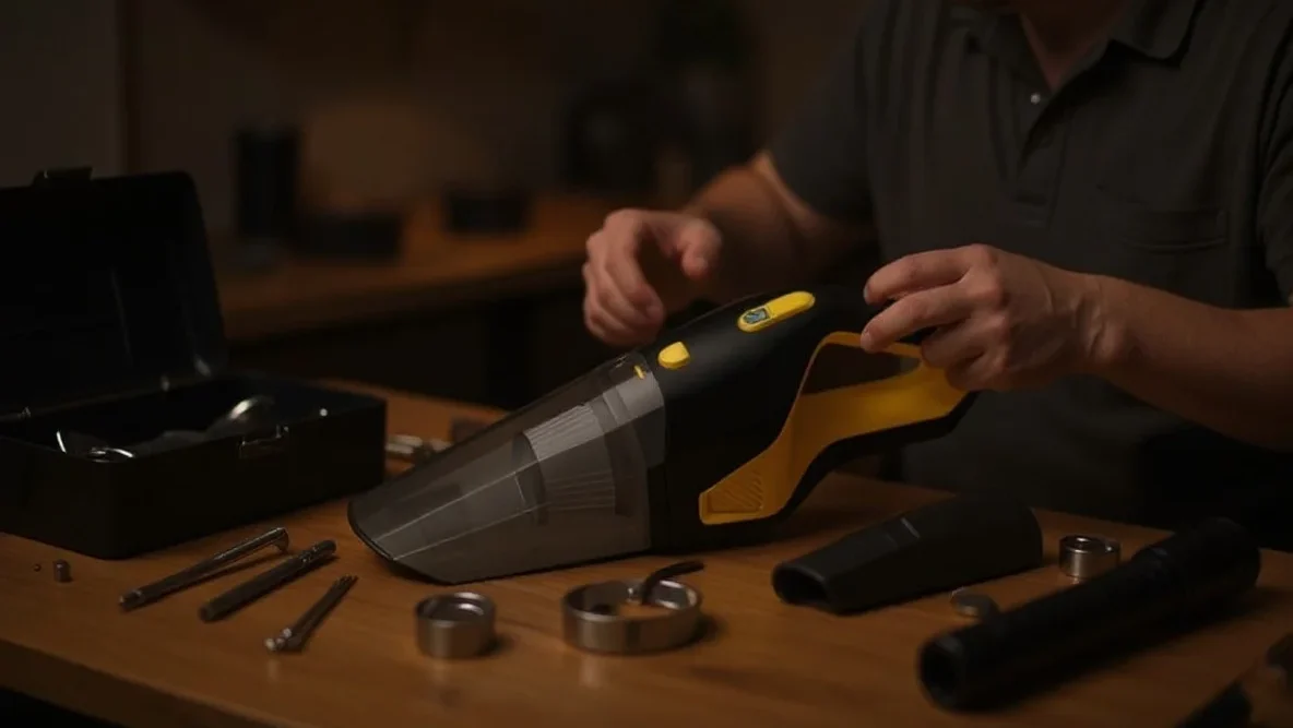
ブロックされたホース試験は、空気の流れが完全に遮断されたときに、掃除機が熱的ストレスをどのように管理するかを評価します。IEC 60335-2-2やISO 7233:2021などの安全規格は、ブロック状態をシミュレートする手順を定義し、危険な温度に達する前にモーターの遮断装置が作動し、ハウジング材が無傷のままであることを保証します。.
異常運転時の安全ベンチマーク
IEC 60335-2-2は、家庭用電気掃除機の安全要件を定めており 掃除機, 、ブロックされたホースを異常運転状態として分類しています。エンジニアはこれらの試験を使用して、モーター巻線やプラスチック筐体が安全温度限界を超える前に、サーマルカットオフやヒューズが電源を遮断することを検証します。.
熱管理システムは、冷却用空気の流れがゼロになったときに 層間剥離や構造変形を防ぐ必要があります。DS/EN 60335-2-69は、産業用ユニットの性能下限値を定義しており、例えば危険な粉塵用ホースでは少なくとも20 m/sの風速を維持することが求められます。.
ISO 7233プロトコルと構造的完全性
ISO 7233:2021は、内部真空に対するホースの耐性を試験する具体的な方法を概説しており、滑らかな中実ボールを使用して完全なブロック状態をシミュレートします。試験手順では、60秒以内に目標の内部真空圧に到達し、その状態を維持してライニングの破損を監視することが要求されます。.
方法Aと方法Bは、透明な気密プレートを使用して、試験中に内部の崩壊や補強材の分離を目視検査できるようにします。ASTM消費者製品規格は、これらのホース固有の機械的試験をより広範な家電製品の安全性評価に統合するための枠組みを提供します。.
吸引力と熱限界のバランス調整
エンジニアは、電気入力の50〜70%が熱に変換されることを考慮して吸引力のバランスを取ります。効果的な設計は、ホース内の最低風速20 m/sを維持し、フィルター負荷を毎時平方メートルあたり200 m³に制限することで、高い吸引力レベルでもプロセス空気の流れがモーターに十分な対流冷却を提供することを保証します。.
気流効率とエネルギー変換熱
真空モーター効率 一般的に50%付近でピークに達するが、多くのシステムは30%に近い値で動作している。このエネルギーギャップは、電気入力の50%から70%が銅巻線と磁性部品内で直接熱エネルギーに変換されることを意味する。設計者は、モーターがこの熱を放散するために吸引に使用されるのと同じプロセス気流に依存しているため、課題に直面する。システムが流量を制限してより高い吸引力を優先すると、同時に対流冷却に利用できる空気量が減少する。.
密閉吸引条件下での運転—気流が完全に遮断された状態—は、最も大きな熱ストレスを生み出す。密閉吸引圧力は、通常の作動流量の4倍に達することが多い。この状態は冷却経路を塞ぎながらモーター負荷を最大化し、適切な熱保護やバイパス機構がなければ内部部品を損傷させる可能性のある急激な温度上昇を引き起こす。.
性能閾値と安全基準
コードレスのスティック掃除機は通常、100〜200エアワットの吸引力範囲を目標とする。アップライト型やキャニスター型は300エアワットに達することがあるが、小型ユニットは高効率の機械式ブラシロールと組み合わせることで、ノズル部でわずか50エアワットでも効果的な掃除を達成できる。これらの目標のバランスを取るには、フィルター負荷限界を厳守する必要がある。エンジニアは、フィルター面積1m²あたりのフィルター負荷を200m³/h未満に保つことを推奨している。この限界を超えると圧力損失が増加し、モーターを高温・低流量状態に追い込む。.
DS/EN 60335-2-69などの安全基準は、産業用および危険性のある粉塵用途における特定の気流要件を定義している。これらの規制は、ホース内の最低流速20m/sを義務付けている。この閾値は、一貫した粉塵輸送と適切なモーター冷却の両方を保証する。40mmホースを通して150m³/hを供給する掃除機は約33m/sの流速を維持するが、50mmホースに切り替えるとその流速は21m/sに低下する。設計者はASTM F2756-09試験を使用して、これらのエネルギー消費変数を温度上昇に対してマッピングし、連続運転中にデバイスが安全な熱限界内に留まることを保証する。.
最終的な所感
エンジニアは、ハンドヘルド設計において吸引力の向上と安全な動作温度の維持の間で常にトレードオフに直面している。小型のモーター容積と高RPMは集中した熱を生み出し、内部電子機器を急速に劣化させたり、プラスチック筐体を溶かしたりする可能性がある。成功しているモデルは、精密加工された気流経路と反応性の熱センサーの組み合わせに依存して、これらの問題を防いでいる。.
これらの安全マージンを維持することは、工場での設計と同様にユーザーのメンテナンスにも依存する。詰まったフィルターや妨害されたホースは、モーターをより激しく動作させると同時に、冷却に必要な空気を遮断する。国際試験基準を遵守することで、目詰まりが発生した場合でも、バッテリーやモーター巻線に恒久的な損傷を与える前にシステムが安全に停止することが保証される。.
よくある質問
スティック掃除機が使用中に熱くなるのはなぜですか?
高速モーターとパワーエレクトロニクスは、小さなプラスチック製の筐体内でかなりの熱を発生させます。ダストボックスが満杯になったりフィルターが目詰まりしたりして空気の流れが制限されると、内部温度が100〜150°Cに急上昇し、恒久的な損傷を防ぐためにサーマルカットオフ(熱安全遮断装置)が作動します。.
過熱した掃除機が冷めるまでどのくらい待つべきですか?
ほとんどのスティック掃除機は、温度ヒューズまたはサーマルカットオフがリセットされるまで30〜60分かかります。本体の電源を切り、ノズルやホースの詰まりを取り除き、フィルターを掃除してモーターの通気口周辺の空気の流れを回復させることで、このプロセスを早めることができます。.
掃除機の熱保護に関する特定の安全基準はありますか?
家庭用掃除機はIEC/EN 60335-1およびIEC/EN 60335-2-2規格に準拠する必要があります。これらの規制により、モーターが故障した場合でも、サーマルカットオフや過電流ヒューズなどの保護装置が、外側の筐体とハンドルを安全な接触温度範囲内に保つことが保証されます。.
掃除機モーターの熱性能はどのように試験されますか?
エンジニアはASTM F2105-21規格を使用して、モーターとファンシステムの性能を評価します。さらに、IEC/EN 60335-2-2に基づく安全試験では、掃除機を異常な動作条件にさらして、内部の安全スイッチが危険な過熱を効果的に防止することを検証します。.

 English
  Español
  Français
  Deutsch
  Português do Brasil
  Русский
  한국어
한국어  日本語
日本語  العربية