 메인 콘텐츠로 건너뛰기 푸터로 건너뛰기
스틱 진공청소기 제조업체들은 80 cm³ 미만의 모터 부피에 300W~600W의 출력을 담아야 하는 점점 더 커지는 과제에 직면해 있습니다. 이러한 고속 브러시리스 모터는 막대한 폐열을 발생시키며, 제대로 관리하지 않으면 민감한 전자 부품을 손상시키거나 안전 온도 한계를 초과할 수 있습니다. 효과적인 스틱 진공청소기 열 관리는 소형 휴대용 케이스 내부의 과열을 방지하기 위해 출력 밀도, 냉각 기류, 재료 내구성 사이의 정밀한 균형을 요구합니다.
이 가이드는 기류 냉각 경로부터 열 차단(TCO) 스위치 통합에 이르기까지 열 안전의 기술적 구성 요소를 탐구합니다. 우리는 모터 온도를 80°C 미만으로 유지하기 위한 고전도성 A356 알루미늄 합금의 사용을 분석하고, 최소 20m/sec의 공기 속도를 유지하는 것이 이물질 운반과 모터 냉각을 모두 보장하는 방식을 살펴봅니다. 또한 IEC/UL 60335-2-2 안전 기준 준수를 확인하기 위한 “호스 막힘” 테스트와 같은 시험 프로토콜을 검토합니다.
작은 공간에서의 고출력이라는 과제
최신 스틱 진공청소기는 80 cm³ 미만의 모터 부피에 300W~600W의 출력을 담아 극한의 출력 밀도를 만들어냅니다. 100,000rpm을 초과하는 고속 브러시리스 모터는 막대한 폐열을 발생시키며, 이는 안전 온도 한계를 초과하거나 내부 전자 부품을 손상시키지 않도록 얇은 플라스틱 하우징을 통해 관리되어야 합니다.
컴팩트 케이스에서의 출력 밀도와 열 유속
2026년의 무선 모터는 300W~500W 사이의 전력을 소비하며, 고급 모델은 600W 이상의 전기 입력을 초과합니다. 이 에너지는 3kg 미만의 휴대용 본체 내부에 위치한 80 cm³ 미만의 모터 부피 내에서 변환됩니다. 그 결과 발생하는 출력 밀도는 기존의 유선 가전제품을 크게 능가하여 좁은 물리적 공간에 열 에너지를 집중시킵니다.
80,000~100,000rpm으로 작동하는 브러시리스 DC 모터는 강한 열을 발생시키는 회전자와 권선 손실을 만들어냅니다. 경량 플라스틱 하우징은 대류 냉각을 위한 표면적이 제한되어 코어에서 열을 분산시키기 어렵습니다. 엔지니어들은 진공청소기 외부를 사용자에게 쾌적하게 유지하면서 이 폐열을 전도하기 위해 최소한의 금속 구조물을 사용합니다.
내부 부품은 산업용 열 챔버에서 발견되는 조건을 모방한 국부적 핫스팟을 견뎌야 합니다. 이러한 온도 구배는 종종 -50°C에서 +250°C까지 다양합니다. 이러한 극한 조건을 관리하려면 고성능 절연재와 특수 기류 경로가 필요하며, 민감한 전자 부품과 배터리 팩을 열화로부터 보호해야 합니다.
규제 준수 및 안전 성능 한계
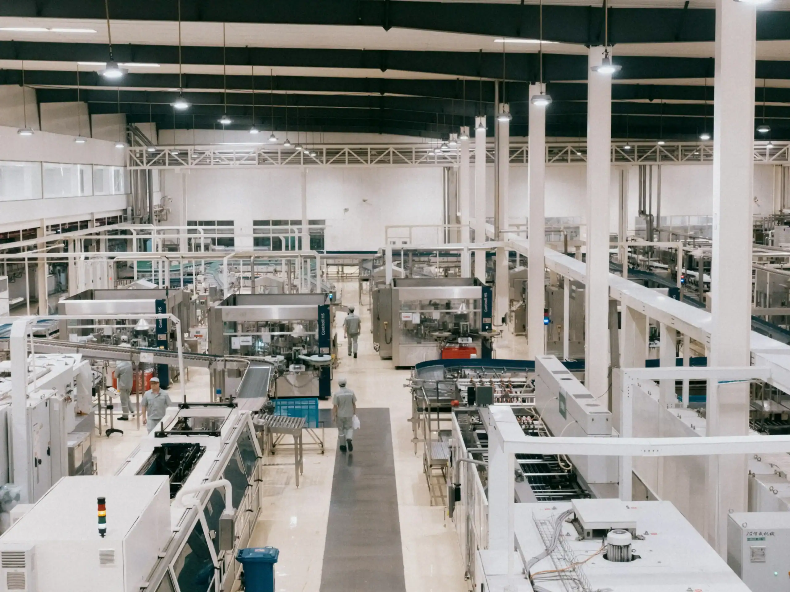
IEC/UL 60335-2-2 표준은 화재 위험과 사용자 부상을 방지하기 위해 표면 온도와 절연 등급에 대해 엄격한 한계를 설정합니다. 이러한 규칙은 고출력 설정에서 장시간 사용 중에도 진공 청소기가 만져도 안전한 상태를 유지하도록 보장합니다. 설계자는 공격적인 성능 목표와 이러한 안전 규정상의 열 여유도를 균형 있게 조정해야 합니다.
ASTM F2105-21은 공기 성능에 대한 특정 측정을 의무화하며, 입력 전력을 온도 상승에 직접 연결합니다. 이는 제조업체가 열 문제를 숨기기 위해 인위적으로 성능을 낮추는 것을 방지합니다. 이 표준은 공기 성능 곡선이 다양한 작동 조건에서 정확하게 유지되어야 하며, 열 관리를 핵심 설계 요구 사항으로 만듭니다.
ASTM F1977-22에 따른 테스트는 필터 압력 강하와 먼지 부하가 모터에 대한 부하를 증가시킨다는 것을 보여줍니다. 필터가 막히면 모터는 흡입력을 유지하기 위해 더 많은 전류를 끌어들이며, 이는 내부 온도를 상승시킵니다. 설계자는 냉각 공기 흐름이 심각하게 제한되는 “호스 막힘” 시나리오에서도 시스템이 안전 여유도를 유지하여 모터가 조기에 열 차단 지점에 도달하지 않도록 보장해야 합니다.
기류 냉각 경로: 통풍구와 덕트 설계
엔지니어는 바이패스 또는 플로우스루 시스템을 사용하여 공기 흐름 경로를 설계함으로써 모터와 배터리 온도를 조절합니다. 2026년까지 모터 배기를 배터리 팩 쪽으로 유도하는 것이 성능을 30% 향상시키는 표준 방법이 되었습니다. 공기 속도를 20m/초 이상으로 유지하면 일관된 흡입력을 보장하고 내부 덕트 내 먼지 축적을 방지할 수 있습니다.
| 성과 지표 | 기술 표준 | 엔지니어링 영향 |
|---|---|---|
| 흡입 호스 속도 | ≥20m/초 | 먼지 운반 및 자동 청소 보장 (DS/EN 60335-2-69) |
| 필터 표면 부하 | m²당 ≤200m³/h | 과도한 저항 및 모터 과열 방지 |
| 배터리 열 이득 | 30% 성능 향상 | 모터 배출 공기를 유도하여 사용 중 배터리 셀을 냉각합니다 |
| 시스템 수주(水柱) 양정 | ≥90인치 | 다음으로 인한 저항을 극복합니다 이 계층형 보관은 프레젠테이션을 체계적으로 유지하고 40HQ 컨테이너 운송 중에 작은 부품이 이동하는 것을 방지합니다. 및 연장 호스 |
모터 냉각 구성: 바이패스 vs. 플로우스루 시스템
바이패스 냉각은 독립 팬을 사용하여 깨끗한 실내 공기를 모터 전기자 주위로 순환시킵니다. 이러한 분리 구조는 모터가 젖거나 오염된 흡입 공기와 접촉하는 것을 방지하며, 업라이트형, 상업용 탱크형, 습식/건식 진공청소기에 필수적입니다. 플로우스루 시스템은 여과된 흡입 공기를 모터 부품 위로 직접 통과시켜 가정용 스틱형 및 캐니스터형 모델에서 더 조용한 작동 프로파일을 제공합니다. 엔지니어는 플로우스루 설계에 열 안전 밸브를 포함하여 퓨즈세이프 역할을 하게 하며, 1차 흡입 경로가 제한될 경우 냉각 공기를 공급하기 위해 밸브가 열립니다.
모터 배출 공기를 배터리 팩 쪽으로 유도하는 전략적 덕팅은 사용 효율과 런타임을 30% 증가시킵니다. 이 방법은 무선 제품의 열 부하를 관리합니다 스틱 청소기 배출된 공기를 활용하여 배터리 셀에서 열을 방출합니다. 밀폐형 시스템은 이러한 기류 집중을 청소 헤드에서 유지하여 이물질 제거에 사용 가능한 분당 입방피트(CFM)를 극대화합니다.
공기 속도 기준 및 압력 요구 사항
흡입 호스는 분진 운반에 관한 DS/EN 60335-2-69 기준을 준수하려면 최소 공기 속도 20m/sec를 유지해야 합니다. 이 특정 속도는 내부 덕트에 이물질이 쌓이지 않고 시스템 내부에 입자가 침전되는 것을 방지합니다. 예를 들어, 40mm 직경 호스를 통해 150m³/h의 공기를 이동시키면 33m/sec의 속도가 생성되어 자체 세척을 위한 최소 안전 요구 사항을 초과합니다.
필터 표면적은 시스템 부담을 피하기 위해 공기 부하를 m²당 200m³/h로 제한해야 합니다. 필터의 높은 저항은 모터가 더 많은 전류를 소모하게 하여 냉각 경로가 막히면 과열 가능성이 있습니다. 딥 클리닝을 위한 설계 기준은 일반적으로 캐니스터 진공청소기에는 100CFM, 업라이트 모델에는 60CFM을 요구합니다. 90인치 수주 양정 등급은 또한 조밀한 HEPA 필터와 긴 부속품을 통해 공기를 흡입하면서 진공청소기가 이러한 기류 수준을 유지할 수 있도록 보장합니다.
모터 열 차단(TCO) 안전 스위치
열 차단(TCO) 스위치는 일반적으로 65°C에서 180°C 사이의 안전하지 않은 온도에 도달하면 전기 회로를 차단하여 진공 모터를 보호합니다. 시스템은 일반적인 과부하용 리셋 가능한 바이메탈 보호기와 심각한 과열에 대한 최종 안전 장치로 리셋 불가능한 열 퓨즈를 모두 활용합니다.
| 구성 요소 범주 | 기술 사양 | 안전 기능 |
|---|---|---|
| 바이메탈 열 보호기 | 60–180°C; 1–15A @ 250V AC | 재설정 가능한 보호; 과부하 시 개방되고 냉각 후 재설정됩니다. |
| One-Shot Thermal Fuse | 정격 작동 온도 최대 954°C | 영구적인 회로 차단; 중요한 페일세이프 역할을 합니다. |
| 진공 시스템 한계 | 120–150°C 트립 포인트 | 하우징 변형을 방지하고 UL 2111 / EN 60730 규정을 준수합니다. |
바이메탈 열 보호기 및 일회용 퓨즈
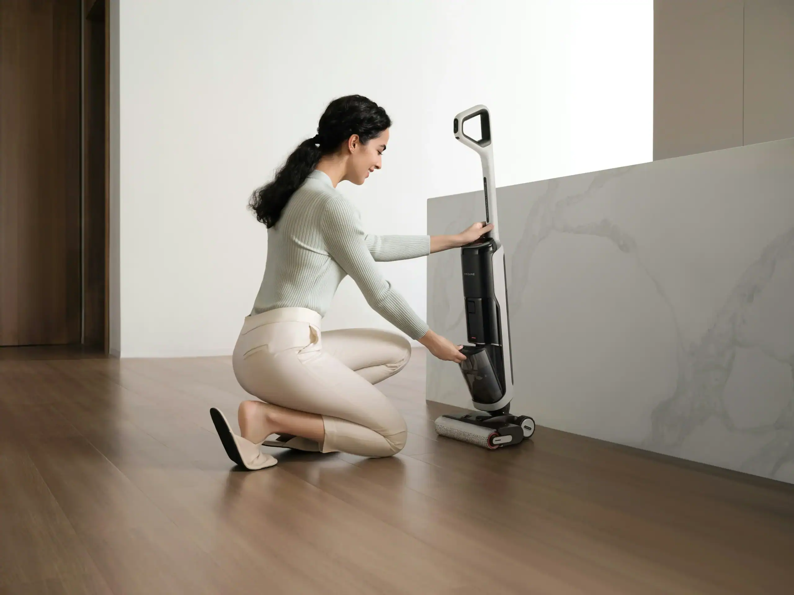
바이메탈 열 보호기는 일시적인 과열 상황에서 전기 회로를 차단하는 리셋 가능한 스위치 역할을 합니다. 이 부품은 모터가 일반적으로 30 ± 15°C의 안전한 차동 온도로 냉각되면 자동으로 닫혀 기기가 다시 작동할 수 있게 합니다. 일회용 열 퓨즈는 모터가 정격 작동 온도를 초과할 때 내부 합금을 용융시켜 전류를 영구적으로 차단함으로써 영구적인 안전 계층을 제공합니다. 이 리셋 불가 메커니즘은 치명적인 고장 발생 시 화재 위험을 방지합니다.
엔지니어는 이러한 부품을 모터 권선 또는 하우징에 직접 통합하여 과부하 또는 회전자 구속 조건에서 구리 온도 상승을 모니터링합니다. HCET와 같은 제조업체는 250V AC에서 1–15A 정격의 과부하 보호기를 생산하며, 이는 코드리스 및 유선 스틱 청소기 모터의 특정 전력 요구 사항과 일치합니다. 코드리스 및 유선 스틱 청소기 모터의 전력 요구 사항. 센서를 모터 코일의 직접적인 열 경로에 배치함으로써 시스템은 전류 급증 또는 공기 흐름 차단에 신속하게 반응합니다.
작동 임계값 및 규제 준수
진공 청소기 애플리케이션의 표준 TCO 차단 온도는 60°C에서 180°C 범위이며, 정밀한 작동을 보장하기 위해 일반적으로 ±5°C의 허용 오차를 갖습니다. 스틱 청소기 시스템은 필터 막힘 시 플라스틱 하우징 변형을 방지하고 접촉 온도 안전성을 유지하기 위해 TCO 트립 포인트를 120–150°C 범위로 설정하는 경우가 많습니다. 이 교정은 내부 열이 모터 권선의 절연 등급 한계를 초과하기 전에 장치가 차단되도록 보장합니다.
UL 2111 및 EN 60730 표준을 준수하면 이러한 열 제어 장치가 가전제품에 대한 엄격한 내구성 및 절연 내력 요구 사항을 충족함을 검증합니다. Calco ASR 시리즈와 같은 부품은 250V / 10A 정격을 제공하여 고흡입력 브러시리스 모터에서 발견되는 피크 전류를 처리하는 데 필요한 용량을 제공합니다. 이러한 규제 프레임워크를 준수함으로써 완전히 막힌 흡입구나 고착된 브러시 롤과 같은 비정상적인 작동 조건에서도 진공 청소기가 안전하게 유지됨을 보장합니다.
맞춤형 고성능 진공 청소기로 브랜드 확장하기

모터 하우징용 내열 재료
엔지니어들은 A356 알루미늄 합금 및 열안정성 엔지니어링 플라스틱과 같이 높은 열전도율과 기계적 강도를 가진 재료를 우선시합니다. 이러한 재료는 내부 작동 온도를 120°C 미만으로 유지하여 절연 파괴를 방지하고 컴팩트한 고흡입력 사이클 동안 구조적 무결성을 보장합니다. 진공 청소기 설계.
고전도성 합금 및 경량 폴리머
A356 및 AlSi10Mg와 같은 알루미늄 합금은 170 W/m·K에 달하는 열전도율을 제공합니다. 이러한 효율성은 집중 작동 중에도 모터 온도를 80°C 미만으로 유지하는 데 도움이 됩니다. A356은 밀도 2.7 g/cm³, 인장 강도 200~300 MPa를 제공하여 고속 회전자를 위한 견고한 프레임을 제공합니다. 내충격성이 우선시되는 애플리케이션의 경우 ADC12 알루미늄은 96~105 W/m·K의 전도율과 300 MPa의 인장 강도의 균형을 제공합니다.
무게에 민감한 휴대용 설계에는 종종 PEEK 또는 나일론과 같은 엔지니어링 플라스틱이 통합됩니다. 이러한 재료는 밀도가 1.2~1.8 g/cm³로 진공 청소기의 전체 질량을 크게 줄이면서 열 변형에 저항합니다. 중부하 상업용 장치에서 스테인리스 스틸 304 하우징은 200°C의 온도 변화와 2 kN의 횡력을 처리합니다. 스테인리스 스틸은 열전도율이 16 W/m·K로 낮지만, 구조적 파손이 허용되지 않는 극한 환경에서 모터를 지지하는 내구성을 제공합니다.
세라믹 코팅 및 정밀 가공 기준
0.2~0.5mm 두께의 열차단 세라믹 코팅은 열유속을 40% 차단합니다. 이 절연층은 모터 권선에서 발생하는 최대 열로부터 민감한 내부 전자 부품을 보호합니다. 일반적으로 15~25µm 두께로 적용되는 아노다이징과 같은 표면 처리는 500시간 이상의 염수 분무 저항성을 제공합니다. 이러한 층은 또한 외부 하우징 표면의 열 복사를 향상시켜 작동 중 수동 냉각을 돕습니다.
정밀 제조를 통해 하우징이 IP65 또는 IP67 환경 보호 기준을 충족합니다. 가공 공정은 Ra 0.8µm 표면 마감과 ±0.02mm 공차를 유지하여 Shore A 70~80 가스켓으로 기밀 밀봉을 만듭니다. 열 부하를 추가로 관리하기 위해 엔지니어들은 5~10mm 간격의 냉각 핀을 통합합니다. 이 설계 선택은 모터 설치 공간을 늘리지 않고 유효 방열 표면적을 30%에서 50%까지 증가시켜 권선 온도가 장기 신뢰성에 필요한 120°C 임계값 미만으로 유지되도록 보장합니다.
막힌 필터가 작동 온도에 미치는 영향
막힌 필터는 모터 방열에 필요한 냉각 공기 흐름을 제한하여 내부 온도가 급격히 상승하게 합니다. 이러한 공기 흐름 감소는 기계적 부하와 전류 소모를 증가시켜 하우징 변형과 모터 권선 고장을 방지하기 위해 열 차단 스위치나 바이패스 밸브가 작동하도록 하는 경우가 많습니다.
공기 흐름으로 인한 과열 메커니즘
진공 모터는 내부 권선에서 열을 방출하기 위해 일정한 흡입 공기 흐름에 의존합니다. 필터가 이물질로 포화되면 시스템을 통과하는 공기량이 크게 감소합니다. 이러한 대류 냉각 손실로 인해 열에너지가 배출구를 통해 배출되지 않고 모터 하우징 내부에 축적될 수 있습니다.
막힌 필터는 팬이 더 높은 압력 손실에 맞서 작동하도록 강제합니다. 성능을 유지하기 위해 모터는 더 많은 전류를 소비하며, 이는 권선의 동손을 통해 추가 열을 발생시킵니다. 스틱 청소기, 이러한 냉각 감소와 전기 부하 증가의 조합으로 외부 케이싱이 빠르게 고온에 도달하며, 안전 센서가 작동하지 않으면 종종 셧다운이나 연기 발생으로 이어집니다.
이러한 조건에서 진공 청소기를 장시간 작동하면 기계 부품에 극심한 스트레스가 가해집니다. 공기 흐름이 제한된 상태에서 20,000Pa에 가까운 흡입 부하로 연속 사용하면 베어링 윤활유의 분해가 가속화됩니다. 이러한 분해는 마찰 증가와 더 높은 작동 온도를 유발하여 결국 모터 고착이나 하우징 변형을 초래합니다.
열 기준 및 진단 임계값
진공 부품에 대한 엔지니어링 표준에는 수명을 보장하기 위한 엄격한 열 제한이 포함됩니다. 산업용 막힘 표시기는 최대 75°C의 매체 온도와 -20°C ~ +60°C 범위의 주변 환경에서 작동하도록 설계되었습니다. 이러한 센서는 필터 양단의 압력 차등을 모니터링하여 시스템이 위험한 과열 상태에 진입하기 전에 진단 경고를 제공합니다.
고급 필터 매체는 종종 극한의 열을 견딜 수 있으며, 일부 고성능 소재는 최대 220°C의 온도에서 사용하도록 등급이 지정됩니다. 모터와 주변 플라스틱 부품이 내열성의 주요 병목 지점 역할을 합니다. 필터 재료 자체가 분해되기 훨씬 전에 모터 수준에서 고장이 발생하므로 공기 흐름 관리는 시스템 안전을 위한 중요한 설계 우선순위가 됩니다.
최신 진공 시스템은 필터 막힘의 위험을 완화하기 위해 열 작동 차단 장치와 바이패스 밸브를 사용합니다. 이러한 부품은 상승하는 열에 반응하여 장치를 차단하거나 모터를 냉각하기 위한 대체 공기 경로를 엽니다. 차압 센서를 구현하면 기계가 필터 포화 상태를 조기에 감지하여 영구적인 손상을 초래하는 임계값에 모터가 도달하는 것을 방지할 수 있습니다.
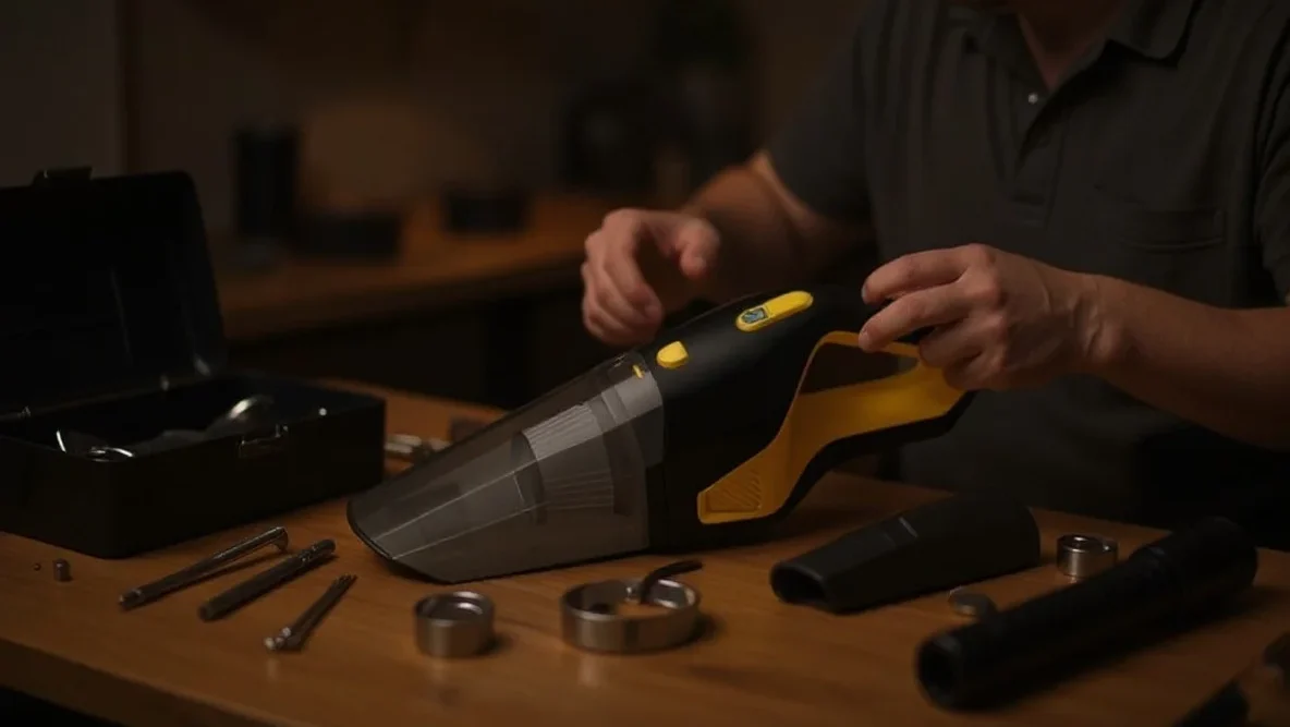
테스트 기준: “호스 막힘” 온도 상승 시험
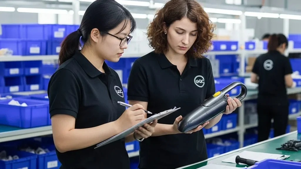
차단된 호스 테스트는 공기 흐름이 완전히 차단되었을 때 진공 청소기가 열 응력을 어떻게 관리하는지 평가합니다. IEC 60335-2-2 및 ISO 7233:2021과 같은 안전 표준은 차단 상황을 시뮬레이션하기 위한 절차를 정의하여 위험한 온도에 도달하기 전에 모터 차단 장치가 작동하고 하우징 재료가 손상되지 않은 상태를 유지하도록 보장합니다.
비정상 작동에 대한 안전 벤치마크
IEC 60335-2-2는 가정용 제품에 대한 안전 요구 사항을 규정하며 진공 청소기, 차단된 호스를 비정상 작동 상태로 분류합니다. 엔지니어들은 이러한 테스트를 사용하여 모터 권선이나 플라스틱 외함이 안전 온도 한계를 초과하기 전에 열 차단 장치와 퓨즈가 전원을 차단하는지 확인합니다.
열 관리 시스템은 냉각 공기 흐름이 0으로 떨어질 때 층간 분리 및 구조적 변형을 방지해야 합니다. DS/EN 60335-2-69는 산업용 장치의 성능 기준을 정의하며, 예를 들어 유해 분진이 있는 경우 호스에서 최소 20 m/s의 공기 속도를 유지해야 합니다.
ISO 7233 프로토콜 및 구조적 무결성
ISO 7233:2021은 매끄러운 고체 볼을 사용하여 완전한 차단을 시뮬레이션하는 호스의 내부 진공 저항 테스트 방법을 설명합니다. 테스트 절차는 60초 이내에 목표 내부 진공 압력에 도달하고 해당 상태를 유지하여 라이닝 파손을 모니터링해야 합니다.
방법 A와 방법 B는 투명한 기밀 플레이트를 사용하여 테스트 중 내부 붕괴 또는 보강재 분리를 육안으로 검사할 수 있도록 합니다. ASTM 소비자 제품 표준은 이러한 호스 특화 기계적 테스트를 더 넓은 가전 제품 안전 평가에 통합하기 위한 프레임워크를 제공합니다.
흡입력과 열 한계의 균형
엔지니어들은 열로 변환되는 50-70%의 전기 입력을 관리하여 흡입력을 균형 있게 조절합니다. 효과적인 설계는 최소 호스 속도 20 m/s를 유지하고 필터 부하를 평방미터당 200 m³/h로 제한하여 높은 흡입 수준에서도 공정 공기 흐름이 모터에 충분한 대류 냉각을 제공하도록 보장합니다.
공기 흐름 효율과 에너지 변환 열
진공 모터 효율 일반적으로 50% 부근에서 최고치에 도달하지만, 많은 시스템은 30%에 더 가깝게 작동합니다. 이 에너지 격차는 전기 입력의 50%에서 70%가 구리 권선과 자기 부품 내에서 직접 열에너지로 변환된다는 것을 의미합니다. 설계자는 모터가 이 열을 발산하기 위해 흡입에 사용되는 것과 동일한 공정 공기 흐름에 의존하기 때문에 어려움에 직면합니다. 시스템이 흐름을 제한하여 더 높은 흡입력을 우선시하면 대류 냉각에 사용할 수 있는 공기량이 동시에 줄어듭니다.
공기 흐름이 완전히 차단되는 밀폐 흡입 조건에서 작동하면 가장 심각한 열 응력이 발생합니다. 밀폐 흡입 압력은 정상 작동 흐름의 4배에 도달하는 경우가 많습니다. 이 상태는 모터 부하를 최대화하면서 냉각 경로를 질식시켜 급격한 온도 상승을 초래하며, 적절한 열 보호 또는 바이패스 메커니즘이 없으면 내부 부품이 손상될 수 있습니다.
성능 임계값 및 안전 기준
코드리스 스틱 진공청소기는 일반적으로 100~200 air watt의 흡입 범위를 목표로 합니다. 업라이트 또는 캐니스터 모델은 300 air watt에 도달할 수 있지만, 소형 모델은 고효율 기계식 브러시롤과 결합하면 노즐에서 50 air watt만으로도 효과적인 청소를 달성할 수 있습니다. 이러한 목표의 균형을 맞추려면 필터 부하 한계를 엄격히 준수해야 합니다. 엔지니어는 필터 부하를 필터 면적 m²당 200 m³/h 미만으로 유지할 것을 권장합니다. 이 한계를 초과하면 압력 강하가 증가하고 모터가 고열, 저유량 상태로 강제됩니다.
DS/EN 60335-2-69와 같은 안전 기준은 산업용 및 유해 분진 응용 분야에 대한 특정 공기 흐름 요구 사항을 정의합니다. 이러한 규정은 최소 호스 속도 20 m/s를 의무화합니다. 이 임계값은 일관된 분진 운반과 적절한 모터 냉각을 모두 보장합니다. 40mm 호스를 통해 150 m³/h를 제공하는 진공청소기는 약 33 m/s의 속도를 유지하지만, 50mm 호스로 전환하면 속도가 21 m/s로 떨어집니다. 설계자는 ASTM F2756-09 테스트를 사용하여 이러한 에너지 소비 변수를 온도 상승에 매핑하여 연속 작동 중에 장치가 안전한 열 한계 내에 유지되도록 합니다.
마지막 생각
엔지니어는 휴대용 설계에서 흡입력 증가와 안전한 작동 온도 유지 사이의 끊임없는 절충에 직면합니다. 작은 모터 부피와 높은 RPM은 내부 전자 부품을 빠르게 저하시키거나 플라스틱 하우징을 녹일 수 있는 집중된 열을 생성합니다. 성공적인 모델은 정밀 가공된 공기 흐름 경로와 반응형 열 센서의 결합에 의존하여 이러한 문제를 방지합니다.
이러한 안전 여유를 유지하는 것은 공장 엔지니어링만큼이나 사용자 유지 관리에 달려 있습니다. 막힌 필터와 막힌 호스는 모터가 더 열심히 일하도록 강제하면서 동시에 냉각에 필요한 공기를 차단합니다. 국제 테스트 기준을 준수하면 막힘이 발생하더라도 배터리나 모터 권선에 영구적인 손상을 일으키기 전에 시스템이 안전하게 종료됩니다.
자주 묻는 질문
스틱 청소기는 사용 중에 왜 뜨거워지나요?
고속 모터와 전력 전자 장치는 작은 플라스틱 하우징 내에서 상당한 열을 발생시킵니다. 먼지통이 가득 차거나 필터가 막혀 기류가 제한되면 내부 온도가 100~150°C까지 급등할 수 있으며, 이때 열 안전 차단 장치가 작동하여 영구적인 손상을 방지합니다.
과열된 청소기가 식을 때까지 얼마나 기다려야 하나요?
대부분의 스틱 청소기는 열 퓨즈 또는 차단 장치가 리셋되는 데 30~60분이 필요합니다. 장치를 끄고 노즐이나 호스의 막힌 부분을 제거하며 필터를 청소하여 모터 통풍구 주변의 공기 흐름을 정상화하면 이 과정을 더 빨리 진행할 수 있습니다.
청소기 열 보호에 대한 특정 안전 기준이 있나요?
가정용 청소기는 IEC/EN 60335-1 및 IEC/EN 60335-2-2 표준을 준수해야 합니다. 이러한 규정은 모터가 오작동하더라도 열 차단 장치 및 과전류 퓨즈와 같은 보호 장치가 외부 케이싱과 손잡이를 안전한 접촉 온도 한도 내로 유지하도록 보장합니다.
청소기 모터의 열 성능은 어떻게 테스트하나요?
엔지니어들은 ASTM F2105-21 표준을 사용하여 모터 및 팬 시스템의 성능을 평가합니다. 또한 IEC/EN 60335-2-2에 따른 안전 테스트는 청소기를 비정상적인 작동 조건에 노출시켜 내부 안전 스위치가 위험한 과열을 효과적으로 방지하는지 확인합니다.

 English
  Español
  Français
  Deutsch
  Português do Brasil
  Русский
  한국어
한국어  日本語
日本語  العربية