메인 콘텐츠로 건너뛰기 푸터로 건너뛰기
SAE J2012와 같은 레거시 표준에 의해 관리되는 영숫자 오류 코드는 사람의 명확성보다 기계 로깅을 우선시하는 “번역 장벽”을 만들어 기술자가 암호화된 데이터를 수동으로 디코딩하도록 강제합니다. 인간의 뇌는 13밀리초 만에 시각 정보를 처리하여 텍스트보다 671% 높은 작업 성공률을 보이므로 추상적인 영숫자 문자열에 의존하는 것은 평균 수리 시간(MTTR)을 늘리고 지원 팀의 인지 부하를 증가시키는 운영상의 부담입니다.
이 가이드는 원시 원격 측정에서 인간 중심 진단으로의 전환을 탐구하며, 다음을 매핑하는 방법을 자세히 설명합니다. ISO 14224 고장 분류 체계를 WCAG 2.2 준수 모션 패턴으로 변환합니다. Siemens WinCC Unified와 같은 산업 플랫폼 내에서 애니메이션 진단 흐름의 구현을 분석합니다. Siemens WinCC Unified 그리고 Rockwell PlantPAx 이를 통해 불필요한 현장 출장을 줄이면서 901%의 첫 접촉 해결률(FCR)을 달성합니다.
기존 오류 코드의 문제점
SAE J2012와 같은 레거시 표준은 기계 로깅을 인간의 명확성보다 우선시하여 지원 팀의 속도를 늦추고 최종 사용자를 혼란스럽게 하는 “번역 장벽”을 만듭니다.
난해한 분류법: 기계 우선 표준이 사용자에게 실패하는 이유
전통적인 진단 표준은 메모리가 제한된 하드웨어 시대에 시작되었습니다. 이러한 시스템은 가독성보다 컴팩트한 데이터 저장을 우선시하여 인간 운영자가 영숫자 문자열을 수동으로 디코딩하도록 강제합니다.
- SAE J2012 차량 ECU에 최적화된 엄격한 5자 구조(예: MAF 센서의 경우 P0101, 속도 센서의 경우 P0500)를 사용합니다.
- ISO 14224 WER(마모), FAT(피로) 또는 MISAL(정렬 불량)과 같은 간결한 식별자가 포함된 문제-원인-조치(P-C-A) 모델을 활용합니다.
- 기술 식별자: 코드는 즉각적이고 실행 가능한 정보를 제공하기보다는 참조 테이블에 대한 포인터 역할을 합니다.
Zapium 연구에 따르면 불균형한 코드 세트는 “사용 불가능한 분석”으로 이어집니다. 코드가 너무 일반적이거나 지나치게 세분화되면 신뢰성 팀이 의미 있는 패턴을 감지하는 능력을 상실합니다.
번역 장벽: 해결 및 지원 UX에 미치는 영향
표준화된 코드는 일반 언어 설명이나 상황별 맥락을 제공하지 못함으로써 핵심 UX 원칙을 위반하는 경우가 많습니다. 이는 속도가 중요한 대규모 B2B 환경에서 운영 마찰을 만듭니다.
- 인지 부하: 상담사는 추상적인 코드를 특정 하드웨어 고장 모드에 정신적으로 매핑해야 하므로 교육 비용과 해결 시간이 증가합니다.
- 맥락 상실: 코드는 정적 하드웨어 상태를 설명하지만(예: EVAP 누출에 대한 P0442), 고장 당시의 사용자 여정이나 환경적 요인은 무시합니다.
- 데이터 불일치: 신뢰성 팀은 ISO 스타일의 세분성이 필요하고, 지원 직원은 단순화된 “문제 프레임”이 필요합니다. 고객을 안내하는 복구 단계.
닐슨 노먼 그룹 지침은 효과적인 오류 메시지가 발생한 상황과 해결 방법을 설명해야 한다고 강조합니다. 기존 코드는 둘 다 하지 못하며, 시스템 언어와 지원 팀의 필요 사이에 장벽 역할을 합니다.
시각적 문제 해결이 더 효과적인 이유
시각 자료는 13밀리초 내에 처리되어 텍스트보다 67% 더 높은 작업 성공률을 달성합니다. 이 방법은 기술자의 추측 작업을 없애고 인간의 눈에 보이지 않는 미세 결함을 식별합니다.
인지 속도 및 작업 성공률 증가
텍스트 중심 매뉴얼에 의존하면 번역 병목 현상이 발생합니다. 인간의 뇌는 텍스트가 따라잡을 수 없는 속도로 이미지를 분석하여, 복잡한 설명을 해독하는 인지 부담 없이 기술자를 식별에서 수리로 이끕니다.
- 처리 속도: 이미지당 13밀리초.
- 작업 성공: 텍스트 전용 지침 대비 67% 더 높은 완료율.
- 일관성: 순서도와 주석이 달린 사진은 문제 해결을 표준화하고 해석 오류를 줄입니다.
1. AVI 및 RVI 기술을 통한 정밀 검사
2. 현대 진단은 인간이 놓치는 것을 보기 위해 특수 하드웨어를 사용합니다. 자동화 및 원격 시스템은 생산을 중단하거나 값비싼 장비 분해 없이 실시간으로 결함을 식별합니다.
- 3. 자동 육안 검사(AVI): 4. 솔더 조인트 및 부품 정렬의 미세 결함을 위한 고해상도 이미징.
- 5. 원격 육안 검사(RVI): 6. 내부 엔진 부품 및 위험 구역에 접근하기 위한 보어스코프 및 드론 엔진 구성 요소 및 위험 구역.
- 8. CMMS 통합: 9. 예측 유지보수 추적을 위한 실시간 사진 업로드 및 시각적 체크리스트.
10. 이러한 기술은 유지보수를 대응식 소방에서 예측 추적으로 전환합니다. RVI를 사용하여 팀은 밀폐된 영역의 손상을 평가하며, 이는 계획되지 않은 다운타임을 줄이고 고장 발생 전에 부식이나 균열을 식별하여 안전성을 향상시킵니다.
UX 디자이너를 위한 애니메이션 오류 코드 설계
12. 애니메이션 오류 코드는 150~500ms의 움직임 단서를 고대비 아이콘과 중복하여 사용하여 WCAG 2.2 표준을 충족하면서 복잡한 진단 인터페이스에서 사용자 복구 시간을 단축합니다.
| 13. 기술 매개변수 | 14. UX 표준 / 요구사항 |
|---|---|
| 15. 애니메이션 지속 시간 | 150–500ms (오류 상태에서는 300–500ms) |
| 색상 대비 (WCAG AA) | 텍스트는 4.5:1, 아이콘 및 테두리는 3:1 |
| 접근성 준수 | WCAG 2.2 SC 2.2.2 및 2.3.3 (동작 비활성화 허용 필수) |
| 시각적 패턴 | 좌우 흔들림(차단), 미세한 맥동(경고) |
동작 타이밍 및 WCAG 접근성 준수
UX 디자이너는 인지도와 자제력의 균형을 맞춰야 합니다. 과도하거나 지속되는 동작은 사용자 피로를 유발하고 움직임에 민감한 사용자에게 전정 기관 문제를 일으킬 위험이 있습니다. 짧은 상호작용 트리거 애니메이션은 인터페이스를 압도하지 않고 즉각적인 피드백을 제공합니다.
- 지속 시간: 동작을 150–500ms로 유지합니다. 실무자는 오류의 경우 300–500ms를 지정하여 눈에 띄되 짜증나지 않도록 합니다.
- 사용자 제어: 필수적이지 않은 애니메이션을 비활성화하는 시스템 수준 설정을 구현하여 WCAG 2.2 성공 기준 2.2.2 및 2.3.3을 준수합니다.
- 대비 비율: 텍스트는 4.5:1 비율을 충족해야 하며, 아이콘이나 입력 테두리 같은 UI 구성 요소는 배경에 대해 3:1 비율이 필요합니다.
컨테이너나 오류 아이콘에 애니메이션을 적용하고, 텍스트 자체에는 적용하지 마세요. 텍스트를 움직이면 사용자가 수정 지침을 읽어야 하는 순간에 가독성이 손상됩니다. 애니메이션으로 시선을 끌고, 메시지는 이해를 위해 정적으로 유지하세요.

시각적 중복성과 진단 상호작용 패턴
색상만으로는 신호가 부족합니다. 남성의 81%가 색각 이상을 경험하기 때문입니다. 고성능 진단 인터페이스는 색상, 아이콘, 움직임을 계층화하여 모든 사용자가 접근할 수 있는 중복된 “코드”를 만듭니다.
- 중복성: 빨간색 신호를 삼각형 안의 느낌표와 같은 표준화된 아이콘과 함께 사용하여 색맹 사용자도 볼 수 있도록 합니다.
- 폼 흔들기: 잘못된 입력을 알리기 위해 좌우 흔들림 패턴을 사용하세요. Stripe에서 사용하는 이 패턴은 제출 오류에 대한 촉각적 피드백을 제공합니다.
- 움직임 계층: 비차단 경고에는 미묘한 맥동을, 중요한 차단 검증 오류에는 뚜렷한 흔들림을 사용하세요.
- 효율성 KPI: 평균 복구 시간과 완료율을 추적하세요. 이러한 지표는 애니메이션이 실제로 사용자가 오류를 더 빨리 수정하도록 돕는지, 아니면 단순히 방해 요소로 작용하는지 검증합니다. 오류 수정 더 빠르게 또는 단순히 방해 요소로 작용하는지.
SAE J2012(DTC)와 같은 기계 중심 표준과 사용자 중심 UI 간의 격차를 해소하세요. 난해한 영숫자 코드(예: P0101)를 특정 움직임 패턴에 매핑하여 기술적 진단을 직관적인 시각 신호로 변환하면 현장 문제 해결 속도를 높일 수 있습니다.
귀하의 브랜드를 위한 프리미엄 OEM/ODM 가정용 진공 솔루션

고객 지원 팀 역량 강화
스마트 진단 플랫폼은 중앙 집중식 원격 해결 및 실시간 원격 측정을 통해 현장 방문을 대체하여 MTTR을 20~50% 줄이고 FCR을 90%로 높입니다.
해결 지표 및 운영 효율성 최적화
고성능 지원 조직은 스마트 원격 링크를 사용하여 복잡한 기술 문제에 대해 80~90%의 첫 접촉 해결(FCR)을 달성합니다. 이 아키텍처는 L2 및 L3 워크로드를 비싼 현장 파견에서 소프트웨어 업데이트와 하드웨어 재설정을 디지털 방식으로 실행할 수 있는 중앙 집중식 원격 팀으로 전환합니다.
- MTTR 감소: 즉각적인 원격 오류 식별을 통해 해결 시간이 20~50% 감소합니다.
- 가동 중단 방지: 예측 모니터링 아키텍처는 산업 및 의료 자산의 계획되지 않은 가동 중단을 30~50% 줄입니다.
- 운영 비용 절감: 원격 수리는 기본 서비스 계층으로 작동하며, 현장 방문은 불가피한 물리적 하드웨어 고장으로 제한됩니다.
기술 계측: 원격 측정, 로그 및 안전한 액세스
표준화된 진단 시스템은 다중 모드 원격 측정을 수집하여 자동화된 근본 원인 안내를 제공합니다. 인간 친화적인 인터페이스를 통해 낮은 수준의 기술 신호를 표시함으로써 L1 에이전트는 엔지니어링 개입 없이 센서 오작동과 컨트롤러 소프트웨어 결함을 구분할 수 있습니다.
- 데이터 채널: 시스템은 센서 수준에서 진동, 온도, 압력 및 모터 전류 서명(MCSA) 데이터를 캡처합니다.
- 보고 표준: 소프트웨어 도구는 구조화된 보고서를 생성합니다.
보고서로그.html매핑되는 파일들 엔지니어링을 위한 ISO 14224 고장 분류 체계에 대한 시스템 상태 에스컬레이션. - 보안 프로토콜: 세션은 TLS 암호화 VPN 터널과 역할 기반 인증을 사용하여 HIPAA 및 EU 데이터 보호 요구 사항을 충족합니다.
- 하드웨어 사양: Smart Pro와 같은 현장 도구는 2GB RAM과 통합 Wi-Fi를 활용하여 전압 변동 중에도 실시간 진단 세션을 유지합니다.
- 표준화된 코딩: 현대 플랫폼은 SAE J2012 진단 문제 코드(DTC)를 사용하여 차량 및 산업 자산 간의 상호 운용성을 보장합니다.
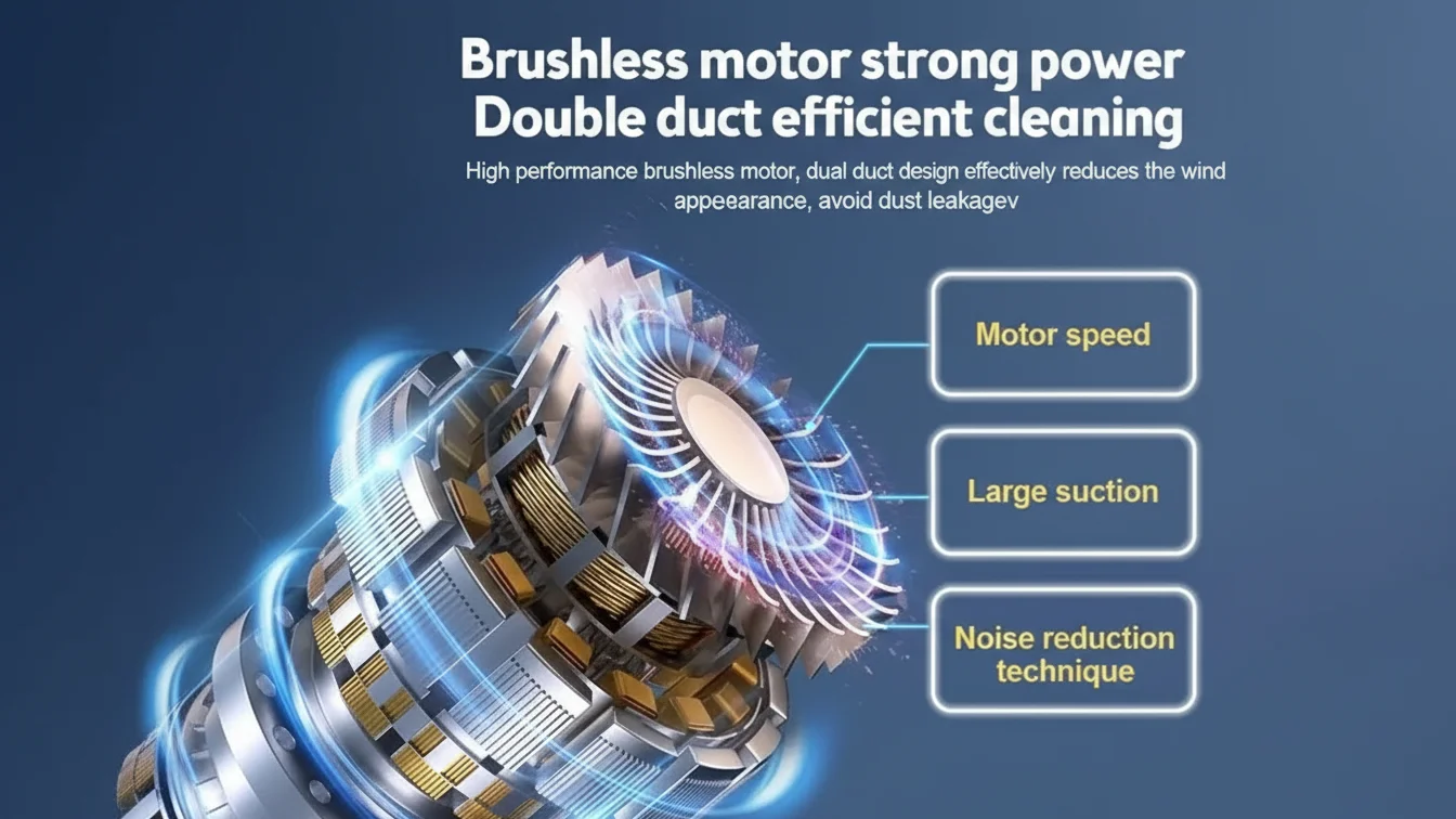
강력한 파워와 효율적인 청소를 위한 듀얼 덕트 디자인의 고성능 브러시리스 모터.
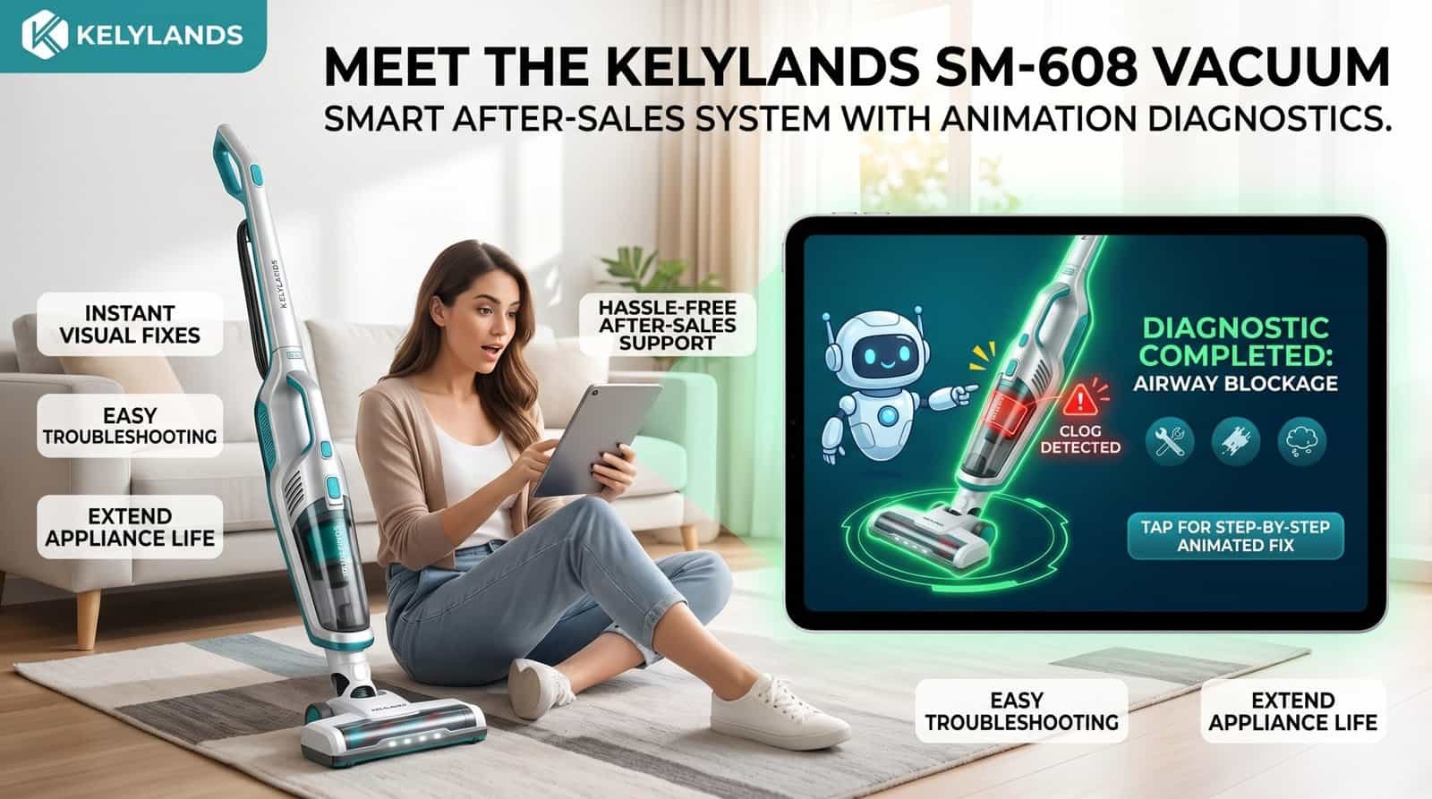
애니메이션 코드가 애프터서비스 비용을 줄이는 방법
애니메이션 코드는 난해한 PLC 펄스와 DTC를 시각적 가이드로 변환하여 비전문가도 결함을 수리할 수 있게 하며, 불필요한 기술자 파견 및 잘못된 부품 발송을 방지합니다.
| 진단 소스 | 원시 데이터 형식 | 시각적 구현 | 운영상의 이점 |
|---|---|---|---|
| LINAK IC 액추에이터 | 10초 디지털 펄스 트레인 | 투명 LED 커넥터 | 비전문가도 즉시 가능한 트리아지 |
| 자동차 (OBD-II) | 5자리 DTC | 구조화된 UI/PID 그래프 | 13~44초 근본 원인 파악 |
| 산업용 HMI | PLC 트레이스 버퍼 | 애니메이션 페이스플레이트 | 엔지니어링 지원 감소 |
원시 원격 측정을 인간 중심 진단으로 변환
작업자가 원시 PLC 트레이스 버퍼를 해석하거나 LED 깜박임을 세도록 강요하지 마십시오. Siemens WinCC Unified와 같은 최신 HMI 시스템은 이제 암호화된 텍스트 로그를 안내 진단 흐름으로 대체합니다. 저수준 신호를 특정 시각적 상태에 매핑함으로써, 기계는 랩톱 연결 없이도 사용자에게 정확히 무엇이 잘못되었는지 알려줍니다.
- 펄스 트레인 매핑: 10초 LINAK IC 액추에이터 신호 프레임을 직관적인 시각적 애니메이션으로 변환합니다.
- LED 상태 표시기: 색상으로 구분된 투명 커넥터(정상은 녹색, 오류는 특정 색상)를 사용하여 초고속 1차 진단 수행.
- 과거 오류 기록: 타임스탬프가 포함된 최근 5개 오류를 시각화하여 간헐적 패턴을 식별하고 예방 유지보수 가능.
서비스 지연 및 현장 비용에 대한 운영 영향
현장 서비스는 주요 수익 저하 요인입니다. 최종 사용자가 5자리 DTC를 잘못 해석하면 잘못된 교체 부품을 배송하거나 “오류 없음” 호출로 기술자를 보내는 경우가 많습니다. Rockwell PlantPAx와 같은 객체 지향 페이스플레이트를 통해 시각화를 표준화하면 전 세계 자산이 모든 지원 담당자가 이해할 수 있는 일관된 시각적 언어를 사용할 수 있습니다.
- OBD-II 타이밍: 전문 스캐너는 13~44초 내에 5자리 DTC와 최대 21개의 라이브 데이터 PID를 가져옵니다. 애니메이션 코드는 비기술 사용자에게도 유사한 속도를 제공합니다.
- 서비스 호출량 감소: 화면 기반 애니메이션을 통한 직접적인 근본 원인 분석으로 불필요한 현장 기술자 방문 방지.
- 물류 정확성: 시각적 상태를 통한 정확한 원격 식별로 잘못된 예비 부품 배송 빈도를 줄입니다.
마지막 생각
기계 우선 영숫자 코드는 잘못된 경제성으로 막대한 숨은 지원 비용을 발생시킵니다. 애니메이션 진단으로 전환하려면 초기 설계 투자가 필요하지만 인간의 해석 오류로 인한 값비싼 현장 출동을 방지할 수 있습니다.
가장 빈번하게 발생하는 다섯 가지 오류 코드를 300~500ms 모션 큐와 고대비 아이콘에 매핑하십시오. 전체 인터페이스를 업데이트하기 전에 지원 상담원과 함께 30일 파일럿을 실행하여 첫 번째 접촉 해결에 미치는 영향을 측정하십시오.
자주 묻는 질문
HMI 화면에 애니메이션 문제 해결 가이드가 표시됩니까?
업계 전체의 IEC, ISA 또는 ISO 표준은 HMI가 애니메이션 문제 해결 가이드를 표시하도록 요구하지 않습니다. (해당 없음). 이는 공급업체별 기능입니다. 제품의 기술 데이터시트 또는 펌웨어 매뉴얼에서 해당 기능의 존재 여부를 확인해야 합니다.
장치 펌웨어가 ‘튜브 막힘'과 ’롤러 걸림'을 구분할 수 있습니까?
현재 HMI 표준 및 프로세스 가이드는 특정 고장 클래스보다는 알람 계층 구조에 중점을 둡니다. 장치가 “튜브 막힘'과 ”롤러 걸림'을 구분하는지 여부는 보편적인 규정이 아닌 제조업체의 펌웨어에 따라 달라집니다.
‘필터 확인’ 알림이 실제 누적 모터 작동 시간을 추적합니까?
공식 표준은 전혀 없습니다. “필터 확인” 알림이 모터 작동 시간과 연동되도록 요구하는 표준은 없습니다.” 고급 진단 기능이 이 데이터를 사용할 수 있지만, 많은 시스템은 더 간단한 트리거에 의존합니다. 항상 OEM의 기술 사양을 확인하여 검증하십시오.