 Zum Hauptinhalt springen Zum Footer springen
Hersteller von Stielsaugern stehen vor einer wachsenden Herausforderung: Sie müssen 300 W bis 600 W Leistung in Motorvolumina von weniger als 80 cm³ packen. Diese bürstenlosen Hochgeschwindigkeitsmotoren erzeugen intensive Abwärme, die empfindliche Elektronik beschädigen oder Sicherheitstemperaturgrenzen überschreiten kann, wenn sie nicht richtig gemanagt wird. Ein effektives Wärmemanagement für Stielsauger erfordert ein präzises Gleichgewicht zwischen Leistungsdichte, Kühlluftstrom und Materialbeständigkeit, um eine Überhitzung in kompakten Handgeräten zu verhindern.
Dieser Leitfaden untersucht die technischen Komponenten der thermischen Sicherheit, von Kühlluftpfaden bis zur Integration von Thermosicherungen (TCO-Schaltern). Wir analysieren die Verwendung von hochleitfähigen Aluminiumlegierungen A356, um Motortemperaturen unter 80 °C zu halten, und untersuchen, wie die Aufrechterhaltung einer Mindestluftgeschwindigkeit von 20 m/s sowohl den Schmutztransport als auch die Motorkühlung gewährleistet. Wir überprüfen auch Testprotokolle wie den “Blocked-Hose”-Test, um die Einhaltung der Sicherheitsnormen IEC/UL 60335-2-2 zu bestätigen.
Die Herausforderung hoher Leistung auf kleinem Raum
Moderne Stielsauger packen 300 W bis 600 W Leistung in Motorvolumina von weniger als 80 cm³ und erzeugen so eine extreme Leistungsdichte. Bürstenlose Hochgeschwindigkeitsmotoren mit über 100.000 U/min erzeugen intensive Abwärme, die durch dünne Kunststoffgehäuse abgeführt werden muss, um Sicherheitstemperaturgrenzen nicht zu überschreiten oder die interne Elektronik zu beschädigen.
Leistungsdichte und Wärmefluss in kompakten Gehäusen
Akkubetriebene Motoren im Jahr 2026 ziehen zwischen 300 W und 500 W, wobei High-End-Modelle eine elektrische Eingangsleistung von über 600 W erreichen. Diese Energie wird in einem Motorvolumen von unter 80 cm³ umgewandelt, das sich in einem Handgerät von weniger als 3 kg Gewicht befindet. Die resultierende Leistungsdichte übertrifft die herkömmlicher kabelgebundener Geräte erheblich und konzentriert thermische Energie auf einer kleinen physischen Fläche.
Bürstenlose Gleichstrommotoren mit 80.000 bis 100.000 U/min erzeugen Rotor- und Wicklungsverluste, die intensive Wärme generieren. Leichte Kunststoffgehäuse bieten nur eine begrenzte Oberfläche für konvektive Kühlung, was es schwierig macht, die Wärme vom Kern abzuleiten. Ingenieure verwenden minimale Metallstrukturen, um diese Abwärme zu leiten und gleichzeitig die Außenseite des Saugers für den Benutzer angenehm zu halten.
Interne Komponenten müssen lokalen Hotspots standhalten, die Bedingungen in industriellen Thermalkammern nachempfinden. Diese Gradienten liegen oft zwischen -50 °C und +250 °C. Die Bewältigung dieser Extreme erfordert Hochleistungsisolierung und spezielle Luftführungspfade, um empfindliche Elektronik und den Akkupack vor thermischer Degradation zu schützen.
Regulatorische Konformität und Sicherheitsleistungsgrenzen
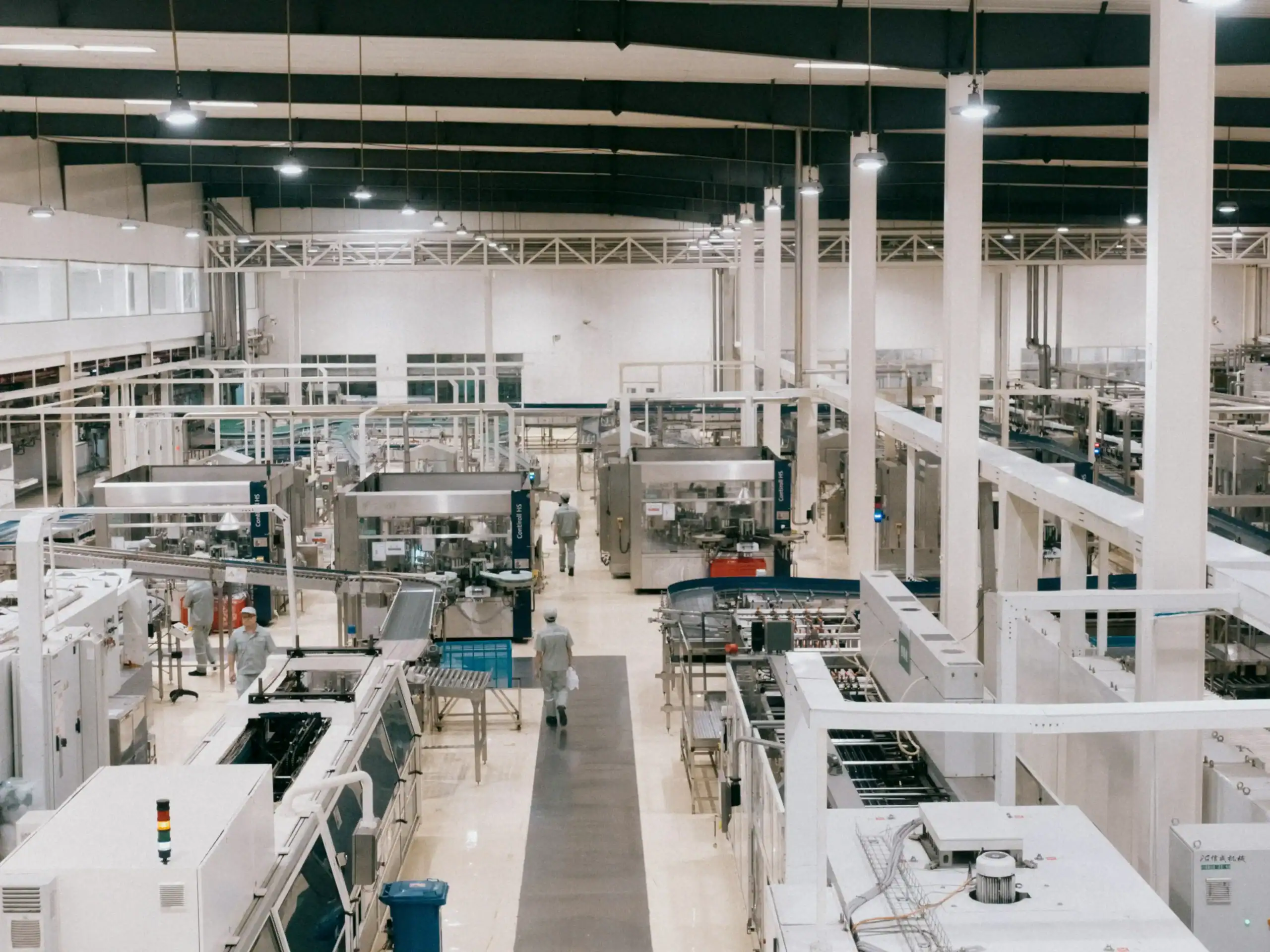
Die Normen IEC/UL 60335-2-2 legen strenge Grenzwerte für Oberflächentemperaturen und Isolationsklassen fest, um Brandgefahren und Verletzungen von Benutzern zu verhindern. Diese Regeln stellen sicher, dass der Staubsauger auch bei längerem Gebrauch mit hoher Leistungseinstellung sicher berührbar bleibt. Konstrukteure müssen ambitionierte Leistungsziele mit diesen sicherheitsbedingten thermischen Reserven in Einklang bringen.
Die Norm ASTM F2105-21 schreibt spezifische Messungen der Luftleistung vor und setzt die Eingangsleistung direkt mit dem Temperaturanstieg in Beziehung. Dies verhindert, dass Hersteller die Leistung künstlich absenken, um thermische Probleme zu verbergen. Die Norm verlangt, dass Luftleistungskurven unter verschiedenen Betriebsbedingungen präzise bleiben, was das Wärmemanagement zu einer zentralen Konstruktionsanforderung macht.
Tests gemäß ASTM F1977-22 zeigen, dass Filterdruckabfälle und Staubbeladung die Motorlast erhöhen. Wenn Filter verstopfen, zieht der Motor mehr Strom, um die Saugleistung aufrechtzuerhalten, was die Innentemperaturen ansteigen lässt. Konstrukteure müssen sicherstellen, dass das System auch bei Szenarien mit “blockiertem Schlauch”, bei denen der Kühlluftstrom stark eingeschränkt ist, Sicherheitsmargen einhält und der Motor seinen thermischen Abschaltpunkt nicht vorzeitig erreicht.
Kühlluftpfade: Gestaltung von Lüftungsöffnungen und Kanälen
Ingenieure gestalten Luftströmungswege entweder mit Bypass- oder Durchflusssystemen, um Motor- und Batterietemperaturen zu regulieren. Bis 2026 ist die Ableitung der Motorabluft auf die Batteriepakete zu einer Standardmethode geworden, um die Leistung um 30 % zu steigern. Die Aufrechterhaltung einer Luftgeschwindigkeit über 20 m/s gewährleistet eine konstante Saugleistung und verhindert Staubablagerungen in internen Kanälen.
| Leistungskennzahl | Technische Norm | Technische Auswirkung |
|---|---|---|
| Saugschlauchgeschwindigkeit | ≥20 m/s | Gewährleistet Staubtransport und Selbstreinigung (DS/EN 60335-2-69) |
| Filterflächenbelastung | ≤200 m³/h pro m² | Verhindert übermäßigen Widerstand und Motorüberhitzung |
| Thermischer Batteriegewinn | 30 % Leistungssteigerung | Directs motor outlet air to cool battery cells during use |
| System Water Lift | ≥90 inches | Overcomes resistance from HEPA-Filter and extended hoses |

Motor Cooling Configurations: Bypass vs. Flow-Thru Systems
Bypass cooling employs an independent fan to circulate clean room air around the motor armature. This separation prevents the motor from contacting wet or dirty intake air, which is essential for uprights, commercial tanks, and wet/dry vacuums. Flow-thru systems route filtered intake air directly over the motor components, providing a quieter operation profile for household stick and canister models. Engineers include thermal safety valves in flow-thru designs to act as a failsafe, opening to provide cooling air if the primary suction path becomes restricted.
Strategic ducting that directs motor outlet air toward the battery pack increases usage efficiency and runtime by 30%. This method manages thermal loads in cordless Stielstaubsauger by utilizing the exhausted air to dissipate heat from the battery cells. Sealed systems maintain this airflow focus at the cleaning head, maximizing the cubic feet per minute (CFM) available for debris removal.
Air Velocity Standards and Pressure Requirements
Suction hoses must maintain a minimum air velocity of 20 m/sec to comply with DS/EN 60335-2-69 standards for dust transport. This specific velocity ensures internal ducts remain clear of debris and prevents particles from settling within the system. For example, moving 150 m³/h of air through a 40 mm diameter hose generates a velocity of 33 m/sec, exceeding the minimum safety requirements for self-cleaning.
Filter surface area must limit air loading to 200 m³/h per m² to avoid system strain. High resistance at the filter forces the motor to draw more current, leading to potential overheating if cooling paths are obstructed. Design benchmarks for deep cleaning typically require 100 CFM for canister vacuums and 60 CFM for upright models. A 90-inch water lift rating further ensures the vacuum can maintain these airflow levels while pulling air through dense HEPA filters and long attachments.
Thermische Sicherheitsschalter für Motoren (TCO)
Thermal cut-off (TCO) switches protect vacuum motors by breaking the electrical circuit when temperatures reach unsafe levels, typically between 65°C and 180°C. Systems utilize both resettable bimetal protectors for common overloads and non-resettable thermal fuses as a final safeguard against critical overheating.
| Komponentenkategorie | Technische Daten | Safety Function |
|---|---|---|
| Bimetal Thermal Protector | 60–180 °C; 1–15 A @ 250 V AC | Wiederherstellbarer Schutz; öffnet bei Überlast und setzt sich nach dem Abkühlen zurück. |
| One-Shot Thermal Fuse | Nennfunktionstemperatur bis zu 954 °C | Permanente Stromkreisunterbrechung; fungiert als kritische Sicherheitsabschaltung. |
| Grenzwerte des Vakuumsystems | 120–150°C Trip Points | Prevents housing deformation and ensures UL 2111 / EN 60730 compliance. |
Bimetal Thermal Protectors and One-Shot Fuses
Bimetal thermal protectors function as resettable switches that open the electrical circuit during temporary overheating events. These components close automatically once the motor cools to a safe differential, usually 30 ± 15°C, allowing the appliance to resume operation. One-shot thermal fuses provide a permanent safety layer by melting an internal alloy to interrupt current indefinitely when the motor exceeds its rated functioning temperature. This non-resettable mechanism prevents fire hazards in the event of a catastrophic failure.
Engineers integrate these components directly into motor windings or housings to monitor copper temperature rise during heavy load or stalled rotor conditions. Manufacturers like HCET produce overload protectors rated for 1–15A at 250V AC, which match the specific power requirements of cordless and corded stick vacuum motors. By placing the sensor in the direct thermal path of the motor coils, the system reacts quickly to current spikes or airflow blockages.
Operational Thresholds and Regulatory Compliance
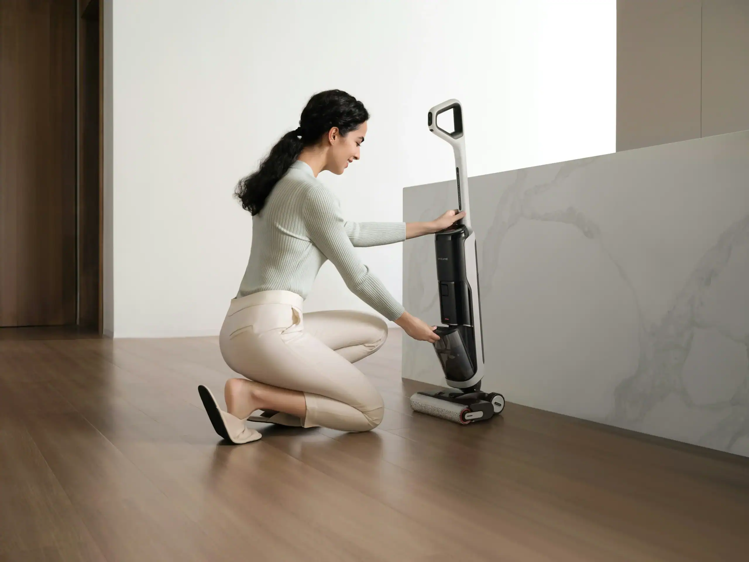
Standard TCO switching temperatures for vacuum applications range from 60°C to 180°C, with a typical tolerance of ±5°C to ensure precise activation. Stick vacuum systems often set TCO trip points in the 120–150°C range to prevent plastic housing deformation and maintain touch-temperature safety during filter blockages. This calibration ensures the device shuts down before the internal heat exceeds the insulation class limits of the motor windings.
Compliance with UL 2111 and EN 60730 standards validates that these thermal controls meet strict endurance and dielectric strength requirements for household appliances. Components such as the Calco ASR series offer ratings of 250V / 10A, providing the necessary capacity to handle the peak currents found in high-suction brushless motors. Adherence to these regulatory frameworks guarantees that the vacuum remains safe under abnormal operating conditions, such as a completely obstructed intake or a seized brush roll.
Skalieren Sie Ihre Marke mit individuellen Hochleistungsstaubsaugern

Hitzebeständige Materialien für Motorgehäuse
Engineers prioritize materials with high thermal conductivity and mechanical strength, such as A356 aluminum alloys and heat-stabilized engineering plastics. These materials keep internal operating temperatures below 120°C, preventing insulation breakdown and ensuring structural integrity during high-suction cycles in compact vacuum designs.
High-Conductivity Alloys and Lightweight Polymers
Aluminum alloys such as A356 and AlSi10Mg provide thermal conductivity reaching 170 W/m·K. This efficiency helps maintain motor temperatures below 80°C, even during intensive operation. A356 offers a density of 2.7 g/cm³ and tensile strength between 200 and 300 MPa, providing a robust frame for high-speed rotors. For applications where impact resistance is a priority, ADC12 aluminum provides a balance of 96–105 W/m·K conductivity and 300 MPa tensile strength.
Weight-sensitive handheld designs often incorporate engineering plastics like PEEK or Nylon. These materials feature densities of 1.2–1.8 g/cm³, significantly reducing the overall mass of the vacuum while resisting thermal deformation. In heavy-duty commercial units, stainless steel 304 housings manage 200°C temperature swings and 2 kN lateral forces. Although stainless steel has lower thermal conductivity at 16 W/m·K, its durability supports motors in extreme environments where structural failure is not an option.
Ceramic Coatings and Precision Machining Standards
Thermal barrier ceramic coatings between 0.2 and 0.5 mm thick cut heat flux by 40%. This insulation layer protects sensitive internal electronics from the peak heat generated by the motor windings. Surface treatments like anodizing, typically applied in layers of 15–25 µm, provide over 500 hours of salt spray resistance. These layers also enhance heat radiation from the external housing surface, aiding in passive cooling during operation.
Precision manufacturing ensures that housings meet IP65 or IP67 environmental protection standards. Machining processes maintain Ra 0.8 µm surface finishes and ±0.02 mm tolerances to create airtight seals with Shore A 70–80 gaskets. To further manage thermal loads, engineers integrate cooling fins with 5–10 mm spacing. This design choice increases the effective dissipation surface area by 30% to 50% without increasing the motor footprint, ensuring winding temperatures stay below the 120°C threshold required for long-term reliability.
Auswirkungen verstopfter Filter auf die Betriebstemperatur
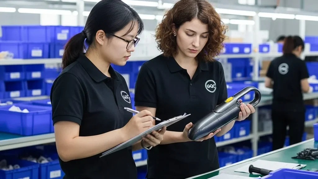
Clogged filters restrict the cooling airflow necessary for motor heat dissipation, causing internal temperatures to rise rapidly. This airflow reduction increases mechanical load and current draw, often triggering thermal cut-off switches or bypass valves to prevent housing deformation and motor winding failure.
Mechanisms of Airflow-Induced Overheating
Vacuum motors rely on a consistent stream of intake air to move heat away from internal windings. When a filter becomes saturated with debris, the volume of air passing through the system drops significantly. This loss of convective cooling allows thermal energy to accumulate within the motor housing rather than being discharged through the exhaust port.
A restricted filter forces the fan to work against a higher pressure drop. To maintain performance, the motor draws more electrical current, which creates additional heat through copper loss in the windings. In Stielstaubsauger, this combination of reduced cooling and increased electrical load causes the external casing to reach high temperatures quickly, often leading to a shutdown or the release of smoke if safety sensors fail to trip.
Operating a vacuum under these conditions for extended periods puts extreme stress on mechanical components. Continuous use at suction loads near 20,000Pa while airflow is restricted accelerates the degradation of bearing lubricants. This breakdown leads to increased friction and even higher operating temperatures, eventually causing the motor to seize or the housing to deform.
Thermal Standards and Diagnostic Thresholds
Engineering standards for vacuum components include strict thermal limits to ensure longevity. Industrial clogging indicators are designed to function with media temperatures up to 75°C and ambient environments ranging from -20°C to +60°C. These sensors monitor the pressure differential across the filter, providing a diagnostic warning before the system enters a dangerous overheating state.
Advanced filter media can often survive extreme heat, with some high-performance materials rated for temperatures up to 220°C. The motor and surrounding plastic components serve as the primary bottleneck for heat tolerance. Failure occurs at the motor level long before the filter material itself degrades, making airflow management a critical design priority for system safety.
Modern vacuum systems use thermally triggered cut-offs and bypass valves to mitigate the risks of a blocked filter. These components react to rising heat by either shutting down the unit or opening an alternative air path to cool the motor. Implementing differential-pressure sensors allows the machine to detect filter saturation early, preventing the motor from reaching the critical thresholds that lead to permanent damage.
Prüfnormen: Der “Blocked-Hose”-Temperaturanstiegstest
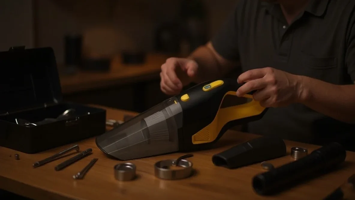
The blocked hose test evaluates how a vacuum manages thermal stress when airflow is completely obstructed. Safety standards like IEC 60335-2-2 and ISO 7233:2021 define the protocols for simulating blockages, ensuring that motor cut-outs trigger and housing materials remain intact before reaching hazardous temperatures.
Safety Benchmarks for Abnormal Operation
IEC 60335-2-2 establishes the safety requirements for household Staubsauger, categorizing a blocked hose as an abnormal operation state. Engineers use these tests to verify that thermal cut-outs and fuses disconnect power before motor windings or plastic enclosures exceed safety temperature limits.
Thermal management systems must prevent delamination and structural deformation when the cooling airflow drops to zero. DS/EN 60335-2-69 defines performance floors for industrial units, such as maintaining at least 20 m/s air velocity in hoses for hazardous dust.
ISO 7233 Protocols and Structural Integrity
ISO 7233:2021 outlines specific methods for testing hose resistance to internal vacuum, utilizing a smooth solid ball to simulate a total blockage. Test procedures require reaching the target internal vacuum pressure within 60 seconds and holding the condition to monitor for lining failure.
Method A and Method B use transparent airtight plates to allow visual inspection for internal collapse or reinforcement separation during the test. ASTM consumer product standards provide the framework for integrating these hose-specific mechanical tests into broader appliance safety evaluations.
Abwägung von Saugleistung und thermischen Grenzen
Engineers balance suction by managing the 50-70% of electrical input that converts to heat. Effective designs maintain a minimum hose velocity of 20 m/s and limit filter loading to 200 m³/h per square meter, ensuring the process airflow provides sufficient convective cooling to the motor even at high suction levels.
Airflow Efficiency and Energy Conversion Heat
Vacuum motor efficiency typically peaks near 50%, though many systems operate closer to 30%. This energy gap means 50% to 70% of electrical input converts directly into thermal energy within the copper windings and magnetic components. Designers face a challenge because the motor relies on the same process airflow used for suction to dissipate this heat. When a system prioritizes higher suction by restricting flow, it simultaneously reduces the volume of air available for convective cooling.
Operating under sealed suction conditions—where airflow is completely blocked—creates the most significant thermal stress. Sealed suction pressure often reaches four times the level of normal working flow. This state chokes the cooling path while maximizing motor load, leading to rapid temperature spikes that can damage internal components without proper thermal protection or bypass mechanisms.
Performance Thresholds and Safety Standards
Cordless stick vacuums usually target a suction range of 100 to 200 air watts. While upright or canister units may reach 300 air watts, smaller units can achieve effective cleaning with as little as 50 air watts at the nozzle when paired with a high-efficiency mechanical brushroll. Balancing these targets requires strict adherence to filter loading limits. Engineers recommend keeping filter load below 200 m³/h per m² of filter area. Exceeding this limit increases pressure drop and forces the motor into a high-heat, low-flow state.
Safety standards such as DS/EN 60335-2-69 define specific airflow requirements for industrial and hazardous dust applications. These regulations mandate a minimum hose velocity of 20 m/s. This threshold ensures both consistent dust transport and adequate motor cooling. A vacuum providing 150 m³/h through a 40 mm hose maintains a velocity of approximately 33 m/s, but switching to a 50 mm hose drops that velocity to 21 m/s. Designers use ASTM F2756-09 testing to map these energy consumption variables against heat rise, ensuring the device remains within safe thermal limits during continuous operation.
Abschließende Gedanken
Engineers face a constant trade-off between increasing suction power and maintaining safe operating temperatures in handheld designs. Small motor volumes and high RPMs create concentrated heat that can quickly degrade internal electronics or melt plastic housings. Successful models rely on a combination of precision-machined airflow paths and reactive thermal sensors to prevent these issues.
Maintaining these safety margins depends as much on user maintenance as it does on factory engineering. Clogged filters and obstructed hoses force motors to work harder while simultaneously cutting off the air they need to stay cool. Adhering to international testing standards ensures that even when a blockage occurs, the system shuts down safely before causing permanent damage to the battery or motor windings.
Häufig gestellte Fragen
Why does a stick vacuum become hot during use?
High-speed motors and power electronics generate significant heat within small plastic enclosures. When airflow is restricted by a full dust bin or a clogged filter, internal temperatures can spike to 100–150 °C, triggering the thermal safety cut-out to prevent permanent damage.
How long should I wait for an overheated vacuum to cool down?
Most stick vacuums require 30 to 60 minutes for the thermal fuse or cut-out to reset. You can speed up this process by switching the unit off, clearing any blockages in the nozzle or hose, and cleaning the filters to restore proper airflow around the motor vents.
Are there specific safety standards for vacuum thermal protection?
Household vacuums must comply with IEC/EN 60335-1 and IEC/EN 60335-2-2 standards. These regulations ensure that protective devices like thermal cut-outs and overcurrent fuses keep the exterior casing and handles within safe touch-temperature limits, even if the motor malfunctions.
How is the thermal performance of a vacuum motor tested?
Engineers use the ASTM F2105-21 standard to evaluate the performance of motor and fan systems. Additionally, safety testing under IEC/EN 60335-2-2 subjects the vacuum to abnormal operating conditions to verify that the internal safety switches effectively prevent hazardous overheating.

 English
  Español
  Français
  Deutsch
  Português do Brasil
  Русский
  한국어
한국어  日本語
日本語  العربية