Saltar al contenido principal Saltar al pie de página
Los equipos de servicio comercial a menudo luchan contra el tiempo de inactividad de los equipos y los riesgos de seguridad causados por cables de alimentación dañados. Las normas OSHA 29 CFR 1926 dictan que cualquier rotura de la cubierta exterior o evidencia de sobrecalentamiento interno requiere una sustitución completa del cable en lugar de un parche temporal. Estos fallos comprometen la eficiencia operativa y exponen a las instalaciones a una responsabilidad significativa si los equipos de servicio no siguen protocolos de reparación profesionales.
Esta guía detalla los requisitos técnicos para restablecer las unidades de vacío a los márgenes de seguridad de fábrica, abarcando desde la selección del enchufe NEMA 5-15P hasta la gestión de la tensión del muelle en carretes retráctiles. Examinamos por qué las unidades comerciales de alto rendimiento requieren conductores de 14 AWG o 12 AWG para soportar cargas de hasta 18 A y ofrecemos un análisis de costes para instalaciones profesionales que suelen situarse entre $60 y $150.
Cuándo reparar y cuándo sustituir los cables de alimentación
Los técnicos evalúan si los daños afectan al cordaje continuo o a los componentes terminales. Las normas OSHA 29 CFR 1926 exigen la sustitución completa del cable en caso de rotura de la cubierta exterior, cobre expuesto o sobrecalentamiento interno. Las reparaciones sobre el terreno se limitan a sustituir los enchufes o conectores dañados por dispositivos listados que coincidan con el calibre y la ampacidad del cable original.
Criterios de seguridad para la sustitución obligatoria del cordón umbilical
OSHA 29 CFR 1926.403(a) dicta el mantenimiento de los cables en condiciones aprobadas. Las reparaciones deben restablecer la rigidez dieléctrica y la protección mecánica originales de fábrica. Esta norma garantiza que cualquier equipo restaurado funcione con los mismos márgenes de seguridad que un conjunto nuevo de fábrica.
La inspección visual desencadena la sustitución obligatoria. Si el cable muestra cobre expuesto, marcas de quemaduras, aislamiento fundido o segmentos aplastados a lo largo de su longitud, los técnicos deben sustituir todo el conjunto. Estos signos indican que la integridad estructural y eléctrica de los conductores o del aislamiento primario ha fallado.
La cinta eléctrica, los tubos termorretráctiles y los empalmes están prohibidos para reparar cortes o abrasiones en la cubierta. Estos métodos no proporcionan una resistencia a la abrasión equivalente ni la rigidez dieléctrica necesaria para cumplir las normas de seguridad. El uso de cinta para cubrir un corte en un cable flexible infringe los protocolos de conformidad, ya que la cinta no puede soportar la tensión mecánica y la flexión del funcionamiento diario.
Los equipos de mantenimiento deben retirar los cables que estén calientes al tacto durante el funcionamiento. La decoloración de las clavijas indica además fatiga interna del conductor o sobrecarga. Estos cambios físicos sugieren una alta resistencia dentro del cable, lo que crea un riesgo de incendio si el cable permanece en servicio.
Especificaciones técnicas para reparaciones a nivel de componente
Las reparaciones sólo de enchufes son admisibles si los daños se limitan a puntas sueltas, rotas o ausentes, mientras que la cubierta principal del cable permanece intacta. Si el aislamiento exterior y el alivio de tensión interno son funcionales, la sustitución del punto de terminación es una alternativa viable al desguace de todo el cable.
La selección de los enchufes de repuesto depende del calibre específico del cable de vacío. Un cable de vacío de 16 AWG requiere un enchufe NEMA 5-15P con una capacidad nominal de 13-15 A a 125 V. El uso de un enchufe con una clasificación inferior a la del componente original puede provocar fallos en los terminales y una acumulación excesiva de calor en la toma de corriente.
Los nuevos dispositivos terminales deben igualar o superar la potencia nominal en vatios y amperios original del aparato. De este modo se garantiza que el hardware pueda soportar el consumo de corriente del motor bajo carga pesada. Los técnicos deben cotejar estas especificaciones con la placa de datos del fabricante para garantizar la compatibilidad y la seguridad.
La polaridad estricta del cableado es obligatoria durante la instalación de los cuerpos de repuesto listados. Mantener las conexiones correctas caliente, neutro y tierra garantiza la seguridad eléctrica continua en entornos de servicio 2026. Los enchufes incorrectamente cableados pueden energizar el chasis del aparato, creando un riesgo significativo de descarga para el operador.
Protocolos de seguridad para la desconexión de la alimentación y la descarga
Los técnicos deben aislar la fuente de alimentación desconectando el aparato y la toma de corriente antes de retirar el enchufe por su cuerpo. El cumplimiento de las normas IEC 60335-2-2 y UL 1017 garantiza que la protección contra corrientes residuales y los bloqueos mecánicos impidan la puesta en marcha accidental o las descargas eléctricas durante el mantenimiento.
Secuencia obligatoria de aislamiento y desconexión eléctrica
Ponemos el aparato en posición OFF en el interruptor de la unidad primaria antes de interactuar con la toma de pared. Esta secuencia evita la formación de arcos eléctricos en los contactos del enchufe. Al desconectar la unidad, retiramos el enchufe de la toma agarrando el cuerpo del enchufe. Tirar del cable en lugar del enchufe daña las conexiones internas de los cables y compromete la integridad estructural del cable con el paso del tiempo.
Las unidades que funcionan con batería requieren un aislamiento total de la alimentación mediante una desconexión de la batería sin herramientas, un requisito de diseño que se encuentra en las normas UL 1017. En los modelos industriales, utilizamos bloqueos mecánicos de los interruptores de alimentación para evitar el accionamiento accidental mientras se accede al cableado interno. Mantenemos siempre un entorno de trabajo seco y nunca tocamos los componentes eléctricos o los interruptores con las manos mojadas para evitar descargas relacionadas con la conductividad.
Normas técnicas de seguridad y protección contra corriente residual
Nos adherimos al marco de seguridad IEC 60335-2-2:2019 para todas las aspiradoras con una potencia nominal de hasta 250 V. Esta norma garantiza que el aislamiento siga siendo eficaz durante toda la vida útil del aparato. Los técnicos verifican que el circuito de alimentación utilice un interruptor diferencial (RCD) ajustado para dispararse a 30 mA en 30 ms. Este nivel de protección es un requisito en entornos industriales ATEX para mitigar los riesgos de fuga a tierra.
El cumplimiento de las normas de seguridad implica confirmar la presencia de advertencias de “Desenchufar antes de reparar” o de posiciones de APAGADO fiables, tal y como exigen las normas UL 1017 y CSA C22.2 nº 243. Inspeccionamos el cable de alimentación en busca de grietas, envejecimiento o exposición del cobre antes de manipularlo, especialmente en unidades de alta aspiración que superan los 20.000Pa y que consumen una corriente significativa. La aplicación de protocolos de limitación de picos de corriente al comprobar los cables reensamblados protege la placa de circuito impreso y el motor de los dañinos picos de corriente iniciales.
Proceso de sustitución de cordones fijos paso a paso
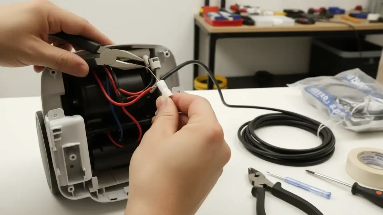
La sustitución de un cable de vacío fijo requiere retirar la placa base y la carcasa del motor para acceder al cableado interno. Los técnicos deben desconectar los cables de 18 AWG -normalmente un cable caliente negro con una tuerca y un cable neutro blanco con un terminal de pala- y transferir el hardware de alivio de tensión al nuevo conjunto de cable con clasificación de 300 V.
| Componente | Especificación | Función |
|---|---|---|
| Cable de repuesto | 18 AWG SJT o SVT (2 hilos) | Alimentación primaria de 300 V |
| Terminales eléctricos | Tuerca (Caliente) / Pala (Neutro) | Puntos de conexión de los cables del motor |
| Hardware de retención | Bota moldeada y soporte de retención | Evita tensiones en el cableado interno |
Desmontaje del chasis y acceso a los componentes
Los técnicos comienzan el procedimiento desenchufando la aspiradora y retirando la placa inferior, el rodillo de cepillos y la correa de transmisión. Estos pasos dejan al descubierto los tornillos principales que sujetan las carcasas del motor y del filtro. La extracción de estos tornillos permite al técnico abrir la cámara de cableado interno donde termina el cable. En los diseños de aspiración en los que el cable de alimentación entra por el mango en lugar de por la base, la extracción de los conjuntos de agarre del mango proporciona el acceso necesario al interruptor eléctrico y a las terminaciones. Documentar con una fotografía el recorrido original de los cables y las posiciones de los terminales garantiza que el proceso de reensamblaje mantenga la polaridad eléctrica y el recorrido mecánico de fábrica.
Terminación del cable y retención mecánica
Las normas de seguridad exigen un cable de repuesto SJT o SVT de 2 conductores y 18 AWG apto para 300 V y 105 °C que se ajuste a las especificaciones del fabricante del equipo original. El técnico desconecta el cable negro caliente de la tuerca del motor y extrae el cable blanco neutro del terminal de pala. Para que la instalación sea satisfactoria, es necesario transferir la funda moldeada de alivio de tensión y el soporte de retención mecánica originales al nuevo cable en su orientación original exacta. Estos herrajes protegen las conexiones internas del motor de fuerzas de tracción externas. Una vez que el técnico fija los nuevos conductores a los cables del motor, debe verificar que el recorrido del cable no presenta ningún punto de aprisionamiento antes de sellar la carcasa y comprobar el funcionamiento de la unidad.
Amplíe su marca con la fabricación experta de aspiradores domésticos OEM/ODM

Procedimientos especializados para conjuntos de cables retráctiles
Los conjuntos de cables retráctiles utilizan un tambor accionado por resorte y un sistema de trinquete para gestionar los cables SJTOW 16/3 o 12/3. El mantenimiento de estos módulos requiere gestionar la energía almacenada desenrollando completamente el muelle y garantizar que las piezas de repuesto mantengan los valores nominales de 125 V/15 A y la continuidad de la conexión a tierra de 3 hilos para cumplir las normas NEC y UL en 2026.
| Especificaciones del cable | Características eléctricas | Uso típico |
|---|---|---|
| 16/3 SJTOW | 10 A / 125 VCA | Herramientas ligeras (33-50 pies) |
| 12/3 SJTOW | 15 A / 125 VCA | Equipo pesado (65 pies) |
Arquitectura mecánica y control de la tensión de los muelles
Los componentes internos del herraje incluyen un muelle espiral plano, un conjunto de tambor giratorio y un eje central de soporte. Estas piezas facilitan la gestión del cable mediante un mecanismo de trinquete y pestillo que ofrece múltiples posiciones de bloqueo. Los técnicos identifican estas posiciones escuchando clics audibles durante la extensión del cable. Para garantizar la seguridad durante el servicio, destensamos completamente el tambor de resorte antes de abrir la carcasa del conjunto. Esto evita la liberación repentina de la energía mecánica almacenada. El módulo de “parada en cualquier punto” regula la velocidad del cable durante el retorno, lo que evita el desgaste del borde del aislamiento y protege el muelle interno de daños por impacto.
Especificaciones eléctricas y normas de montaje
Los procedimientos de servicio requieren la instalación de cables flexibles SJTOW 16/3 ó 12/3 clasificados para un funcionamiento a 125 VCA. Mantenemos valores nominales de corriente entre 10 A y 15 A para garantizar que los herrajes de repuesto coincidan con los requisitos de carga del fabricante del equipo original. Para la instalación estructural, utilizamos orificios pasantes de Ø 8,5 mm para anclar los soportes de montaje de la bobina a los elementos que soportan la carga. El montaje en paneles de yeso por sí solo es insuficiente para el par generado durante la extensión del cable. La verificación final consiste en comprobar la continuidad de la conexión a tierra de 3 hilos desde el enchufe hasta el chasis interno, lo que garantiza que la reparación cumple las normas de seguridad NEC y OSHA para equipos eléctricos conectados a tierra.
Selección del calibre de cable y el tipo de clavija correctos
Una sustitución segura requiere que el amperaje del aparato se ajuste a las normas UL 62, normalmente utilizando conductores 16 AWG para cargas de 13 A. Los técnicos deben verificar el tipo de aislamiento, como SVT para servicio ligero o SJT para servicio duro junior, al tiempo que se aseguran de que la clasificación del enchufe cumple o supera la capacidad del cable.
Clasificaciones y capacidades de uso de los cables UL 62
Las normas UL 62 utilizan códigos alfanuméricos específicos para clasificar los cables de servicio de aspiradoras en función de su aislamiento y el entorno previsto. La designación “V”, que se encuentra en los tipos SV y SVT, identifica los cables clasificados específicamente para aplicaciones de vacío de 300 V. Estos cables mantienen unos diámetros de cubierta totales precisos, como de 5,8 mm a 6,9 mm para cables de 3 conductores 18 AWG, lo que garantiza que encajen con seguridad a través de las arandelas de alivio de tensión de fábrica y los anclajes internos de la carcasa.
Las designaciones SJ y SJT indican clasificaciones de servicio duro inferiores. Aunque siguen siendo aptos para 300 V, estos cables tienen cubiertas más gruesas que los modelos SVT para soportar mayores esfuerzos mecánicos y la abrasión frecuente. Para equipos de limpieza industriales pesados o de construcción, los cables de tipo S proporcionan una clasificación de servicio extra duro de 600 V y ofrecen el máximo nivel de durabilidad frente al aceite, los productos químicos y el desgaste físico extremo en entornos de trabajo exigentes.
Dimensionado de conductores AWG para limitaciones de amperaje y longitud
La selección del grosor del conductor requiere adecuar el calibre al consumo total de amperios del aparato para evitar fallos térmicos. Los conductores de 18 AWG soportan hasta 10 A, lo que es adecuado para pequeñas unidades portátiles o aspiradoras de baja potencia. La mayoría de las aspiradoras domésticas estándar de 13 A utilizan conductores de 16 AWG para proporcionar una capacidad suficiente y, al mismo tiempo, mantener la flexibilidad necesaria para maniobrar durante los ciclos de limpieza.
Las unidades comerciales de alto rendimiento que consumen entre 15 A y 18 A necesitan conductores de 14 AWG o 12 AWG para evitar el sobrecalentamiento durante periodos prolongados de funcionamiento. La eficiencia del motor también depende de la gestión de la caída de tensión; los cables de más de 15 metros suelen requerir un calibre mayor para compensar la resistencia y garantizar que el motor reciba toda la potencia. Los técnicos deben comprobar que la capacidad nominal del enchufe coincide con la capacidad del cable, por ejemplo combinando un enchufe NEMA 5-15P de 15 A con un cableado SJT de 14 AWG, para garantizar que todo el sistema de suministro eléctrico se mantiene dentro de los límites de funcionamiento seguro.
Resolución de problemas eléctricos comunes en la reparación de postes
Los fallos eléctricos posteriores a la reparación suelen deberse a reconexiones incompletas del cableado, cortocircuitos residuales en el cabezal de vacío o interruptores de seguridad activados. Los técnicos los resuelven aislando la unidad de motor de los accesorios y realizando pruebas precisas con multímetros en los circuitos de baja tensión, los sensores de efecto Hall y los condensadores de arranque para garantizar unos estándares de rendimiento óptimos en 2026.
Aislamiento del sistema y comprobaciones preliminares del circuito
Aislamos la unidad de potencia retirando la manguera y la varilla para determinar si el cortocircuito se origina en el cabezal de vacío o en el cableado interno del motor. Los técnicos desconectan el disyuntor principal y comprueban el estado del dispositivo de corriente residual (RCD) para asegurarse de que la fuente de alimentación proporciona un suministro constante de 230 VCA. Este paso elimina las fluctuaciones externas de energía como causa potencial de fallo del sistema.
Si se cortocircuitan los contactos de baja tensión en la entrada de pared o en la unidad de alimentación, se comprueba si se activa el relé del motor. Este proceso aísla eficazmente los fallos en el interruptor de la maneta o en el cableado de la manguera. También controlamos la temperatura ambiente del equipo para asegurarnos de que se mantiene dentro del intervalo de 40° a 104°F, lo que evita la sobrecarga térmica durante las pruebas posteriores a la reparación y la validación operativa.
Diagnóstico del multímetro y calibración de la tensión del sensor
Medimos las salidas del sensor de efecto Hall para confirmar tensiones entre 7,5-10 VCC y 21-24 VCC durante diferentes estados de alimentación. Las pruebas de rotación deben mostrar menos de 1 VCC de variación para pasar la calibración. La comprobación de cortocircuitos internos en los condensadores de funcionamiento y la comprobación de soldaduras en los contactos del relé de arranque implican la supervisión del consumo de amperios inmediatamente después del encendido del motor para detectar irregularidades.
Los técnicos verifican los circuitos de baja tensión de 24 V y 230 VCA en el lado de carga del contactor para garantizar que todos los enclavamientos de seguridad funcionan sin resistencia. Aplicamos estrictos protocolos de conexión a tierra para mitigar los riesgos de descarga electrostática. Esto protege los componentes sensibles de las placas de circuito impreso de potenciales corporales que a menudo superan los 4.000 V durante la manipulación manual y el sondeo.
Implantación de un programa de renovación profesional
Los programas de reacondicionamiento profesional integran registros de mantenimiento trimestrales y pruebas de rendimiento documentadas. Siguiendo normas como Green Seal GS-42 y NADCA ACR, los equipos de servicio garantizan que las unidades cumplan con una eficiencia de filtración HEPA de 99,97% y niveles de ruido por debajo de 70 dBA, manteniendo el cumplimiento de los protocolos de seguridad IEC para uso profesional en 2026.
Marcos normativos y documentación de mantenimiento
Los equipos de servicio adoptan las normas GS-42 del Sello Verde para establecer el mantenimiento documentado trimestral de todos los equipos de limpieza motorizada. Estos protocolos garantizan que cada máquina funcione dentro de los parámetros de rendimiento certificados durante toda su vida útil. La aplicación de las normas ACR de la NADCA proporciona un marco para las inspecciones previas y posteriores a la reparación, garantizando que el alcance del trabajo siga siendo transparente y coherente en toda la flota.
Los intervalos de mantenimiento obligatorios dictan la sustitución de la bolsa y el recipiente cuando las unidades alcanzan la mitad de su capacidad. Esta práctica evita esfuerzos innecesarios del motor y mantiene la máxima potencia de aspiración. La formación del personal utiliza marcos de inspección IICRC para reforzar los métodos acreditados por ANSI, mientras que los registros de mantenimiento detallados realizan un seguimiento del historial específico de sustituciones de cables, cambios de filtros y actualizaciones de etiquetas de seguridad de cada unidad.
Verificación del rendimiento y certificación de la seguridad
Los técnicos verifican que los sistemas de filtración HEPA capturan el 99,97% de partículas de 0,3 μm, cumpliendo estrictamente la norma RRP de la EPA de EE.UU. (40 CFR 745.83). Estas pruebas garantizan que las unidades reacondicionadas contienen eficazmente el polvo peligroso y evitan las fugas de derivación durante el funcionamiento. Otras pruebas confirman que los niveles de ruido se mantienen por debajo del umbral de 70 dBA exigido por el Carpet and Rug Institute para proteger la salud del operario y cumplir las normas de limpieza profesional.
El proceso de reacondicionamiento ajusta la construcción mecánica a las normas IEC 60335-2-69 para aspiradoras industriales en seco y húmedo. Los filtros de alta eficacia instalados durante el mantenimiento requieren una validación con respecto a las clasificaciones EN 1822 para garantizar un verdadero rendimiento HEPA. Para aplicaciones industriales especializadas, las comprobaciones de certificación ATEX confirman que el equipo es seguro para su uso en entornos que contengan polvo combustible o explosivo.
Reflexiones finales
Los técnicos deben dar prioridad a las normas de seguridad establecidas a la hora de decidir entre reparaciones menores y la sustitución completa del cable. El cumplimiento de las directrices de OSHA y UL 62 garantiza que los equipos sigan siendo seguros para los operarios y limita la responsabilidad de los proveedores de servicios. El uso de los calibres de cable correctos y el seguimiento de protocolos de polaridad estrictos mantienen los aspiradores en funcionamiento de forma eficiente y evitan riesgos eléctricos en entornos comerciales de alta demanda.
La implantación de programas estructurados de mantenimiento y reacondicionamiento ayuda a las organizaciones a prolongar la vida útil de sus flotas de limpieza al tiempo que cumplen la normativa 2026 sobre seguridad y medio ambiente. Una gestión y documentación adecuadas del cableado reducen el tiempo de inactividad operativa y garantizan que cada unidad funcione según las especificaciones de fábrica. Este enfoque técnico transforma las reparaciones rutinarias en una estrategia integral para la fiabilidad de la flota y el cumplimiento de las normas de seguridad.
Preguntas frecuentes
¿Es seguro reparar un cable de aspiradora dañado con cinta aislante?
Las autoridades de seguridad no consideran que encintar un cable dañado sea una solución permanente o segura. Los propietarios deben retirar del servicio los aparatos dañados y sustituir el cable por completo para evitar riesgos de incendio y descargas eléctricas.
¿Qué calibre deben tener los cables de las aspiradoras?
Para las típicas aspiradoras domésticas y comerciales ligeras que consumen entre 12 y 15 A, la norma industrial especifica un cable flexible de 3 conductores y 14 AWG (como 14/3 SJT o SGT). Esto cumple los requisitos del artículo 400.5 de NEC para potencias nominales de 15 A.
¿Cuánto costará la sustitución profesional del cable de la aspiradora en 2026?
Una instalación profesional completa suele costar entre $60 y $150. Las piezas de repuesto por sí solas suelen oscilar entre $30 y $80, dependiendo de la longitud del cable y de si el técnico utiliza una pieza certificada OEM.
¿Por qué se calienta el enchufe o el cable de la aspiradora durante su uso?
El calentamiento suele indicar una resistencia eléctrica elevada. Esto ocurre cuando la corriente supera la capacidad nominal del cable, cuando se utiliza un enchufe de 15 A de tamaño inferior para un motor de alto amperaje o cuando los contactos internos sueltos crean un riesgo de incendio.
¿Puedo sustituir el enchufe de una aspiradora sin ayuda profesional?
Una persona competente puede instalar un enchufe nuevo, aunque las directrices de seguridad recomiendan precaución. Si un enchufe moldeado presenta daños, debe cortarlo e instalar un enchufe de repuesto de 15 A o 20 A, siguiendo estrictamente los protocolos de cableado y fusibles.
¿Dónde puedo conseguir cables de repuesto para aspiradoras portátiles?
Recomendamos adquirir los cables a través del programa de piezas autorizadas del fabricante o de un mayorista especializado. El uso de piezas originales aprobadas garantiza que el recambio se ajuste a la clasificación eléctrica específica y a las certificaciones de seguridad del aparato original.