 Saltar al contenido principal Saltar al pie de página
Los ingenieros que gestionan una carga térmica de 600 W enfrentan una penalización física rigurosa: cada aumento de 40 °C por encima de las condiciones operativas estándar provoca una pérdida de potencia del 10 %. Se requiere mantener las temperaturas de la placa base estrictamente dentro del rango de 40 °C a 85 °C para sostener una eficiencia del 93.5 % y evitar fallos estructurales en recintos donde los termoplásticos de ingeniería como el ABS alcanzan su Temperatura de Deflexión Térmica (HDT) a solo 85 °C.
Este informe técnico describe 7 protocolos de Gestión Térmica para módulos de alta fiabilidad como el LCC600 y el GSK600A. Evaluamos marcos de diseño mediante análisis utilizando IPC-2152 para trazas de alta carga y MIL-STD-461F para cumplimiento de EMI, asegurando que el hardware mantenga un MTBF superior a 100 000 horas, evitando el colapso viscoelástico y la rotura por fluencia de componentes poliméricos críticos.
Comprensión de la Carga Térmica de 600 W
Gestionar una carga térmica de 600 W requiere mantener las temperaturas de la placa base entre 40 °C y 85 °C para lograr una eficiencia superior al 90 % y evitar la reducción de potencia en aplicaciones industriales de alta fiabilidad.
Parámetros Clave de la Entrega de Potencia de 600 W y la Eficiencia
Una clasificación de 600 W define la salida continua máxima para módulos como el LCC600 y el GSK600A. Estos sistemas suelen depender de un solo riel de +12 V que entrega 50 A para mantener la estabilidad bajo carga completa.
- Eficiencia: Varía del 87 % al 93.5 % a carga completa.
- Límite térmico: Temperatura de la placa base de 85 °C sin reducción para modelos de alta fiabilidad.
- Opciones de Voltaje: Variantes VDC de 12 V, 28 V, 36 V, 48 V.
- Factor de forma: Alturas compactas de 1.57″ a 1.58″ adecuadas para recintos IP65.
Los niveles de calor residual dependen directamente de estas clasificaciones de eficiencia. Los módulos de alta fiabilidad manejan el volumen térmico sin reducir los niveles de salida, siempre que la gestión de la placa base permanezca dentro del rango especificado de 40°C a 85°C.

Estrategias de disipación y normas de seguridad reglamentarias.
Los ingenieros gestionan el calor mediante conducción a través de disipadores integrados o enfriamiento por aire forzado con ventiladores de 120 mm a 1800 RPM. La física dicta una pérdida de potencia de aproximadamente 10% por cada aumento de 40°C por encima de las condiciones operativas estándar.
- Cumplimiento EMI: MIL-STD-461F.
- Sobretensión/ESD: IEC 61000-4-5 (modo común de 6 kV) e IEC 61000-4-2 Nivel 4.
- Protecciones: Circuitos integrados OVP, OTP y SCP.
- Carga estructural: Clasificado para una resistencia de carga de hasta 5400 Pa en módulos exteriores o especializados.
Estas normas evitan fallos de hardware durante escenarios de calor extremo. Priorizar el enfriamiento basado en física, como el aceite dieléctrico para cargas de RF, mejora el MTBF y asegura que la entrega de 600 W sea continua y estable.
Por qué fallan los plásticos: La Física del Colapso
Los plásticos fallan debido a la viscoelasticidad y fluencia dependientes del tiempo, no solo por fusión. El módulo estructural colapsa cerca de la temperatura de transición vítrea, causando fractura frágil bajo cargas muy por debajo de la resistencia a la tracción nominal.
Umbrales térmicos: Transición vítrea (Tg) y Temperatura de deflexión por calor (HDT)
Los termoplásticos de ingeniería pierden rigidez estructural abruptamente al acercarse a su temperatura de deflexión por calor (HDT). Los diseñadores suelen cometer el error de confiar en el módulo de tracción a temperatura ambiente, pero el calor en servicio cambia el comportamiento del material de dúctil a frágil. Cuando las temperaturas aumentan, las cadenas moleculares obtienen suficiente energía para deslizarse unas sobre otras, provocando una pérdida total de integridad estructural mucho antes de que el material alcance un estado líquido.
- ABS: 85–100°C HDT (a 1,8 MPa)
- Policarbonato (PC): 125–140°C HDT
- Nylon 66 (PA66): 200–230°C HDT (seco)
- PBT: 170–210°C HDT
- uPVC: 70–80°C HDT
El historial de procesamiento también determina los límites de falla. El sobrecalentamiento durante el moldeo por inyección—específicamente con PC, PET y PBT—causa escisión de cadena. Este daño molecular reduce el alargamiento a la rotura, asegurando que la pieza se rompa bajo tensión en lugar de deformarse de manera segura. Una gestión térmica adecuada requiere datos de módulo dependientes del tiempo y la temperatura para tener en cuenta estos cambios en servicio.
Falla sinérgica: Ruptura por fluencia y agrietamiento por tensión ambiental (ESC)
La rotura por fluencia ocurre cuando las cadenas de polímeros se desenredan lentamente bajo una carga sostenida. Este es un “asesino silencioso” en aplicaciones B2B; una pieza puede soportar una carga durante 100 horas pero fallar a las 1,000 horas a pesar de que no haya cambio en el nivel de tensión. Las temperaturas elevadas aceleran este desenredo, reduciendo significativamente el tiempo hasta la rotura en comparación con condiciones ambientales.
El agrietamiento por tensión ambiental (ESC) agrava este riesgo. Cuando un polímero entra en contacto con un fluido que tiene un parámetro de solubilidad similar (dentro de ~20 MPa½), experimenta una iniciación rápida de grietas. Esta interacción puede reducir la vida útil esperada de un componente en varios órdenes de magnitud. Los límites de fatiga también varían enormemente según la estructura molecular del polímero:
- Semicristalinos (PP, POM, PA66): Toleran una deformación del 0.75–1.0% en 10⁶ ciclos.
- Amorfos (PC, PMMA, ABS): Restringido a una deformación de 0.3–0.55% antes de la fractura.
Las tensiones residuales debidas a un espesor de pared no uniforme o a bajas temperaturas del molde actúan como un multiplicador de estas fallas. Cuando la pieza se calienta en el campo, estas tensiones internas se relajan, a menudo provocando grietas inmediatas a lo largo de las líneas de soldadura o insertos metálicos. La validación debe centrarse en datos de fluencia a largo plazo a la temperatura de servicio específica para evitar retiradas catastróficas en el campo.
Estrategias de Diseño para Prevenir Defectos Térmicos
Establecer límites de 35-40°C y seguir IPC-2152 permite una optimización basada en CFD, manteniendo los componentes por debajo de 85°C para evitar fallos estructurales y electrónicos.
| Parámetro de diseño | Estándar / Valor | Objetivo de ingeniería |
|---|---|---|
| Límite ambiental | 35-40°C | Simular entornos automotrices reales |
| Techo del componente | 85°C | Identificar puntos calientes que requieren rediseño |
| Pistas de alta carga | ≥2A / IPC-2152 | Prevenir la delaminación y la falla de las pistas |
| Precisión de la malla | <1% Error RMS | Asegurar la convergencia de la simulación en FEA/CFD |
Establecimiento de límites térmicos y normas de cumplimiento
La confiabilidad térmica depende de definir el entorno antes de elegir el hardware. Si el límite ambiental se establece incorrectamente, el cálculo de enfriamiento falla. Los ingenieros deben establecer una condición límite de 35-40°C para carcasas automotrices y de alto rendimiento para garantizar que componentes como rieles de 50A se mantengan dentro de los límites operativos seguros.
- IPC-2152 e IPC-2221: Estos rigen los cálculos del ancho de las pistas para corrientes ≥2A y optimizan la densidad de las vías térmicas.
- Sección VIII de ASME: Proporciona protocolos de diseño mediante análisis para prevenir la fatiga estructural en componentes presurizados o de alta temperatura.
- Gestión de la placa base: Los módulos de alta potencia de 600W deben mantener una temperatura de placa base de 40-85°C para operar con una eficiencia del 93.5% sin reducción de potencia.
- El umbral de 85°C: Esto sirve como el disparador obligatorio para ajustes de diseño en PCB de alta potencia para prevenir la degradación a largo plazo del MTBF.
Cumplir con estos marcos previene la pérdida de potencia del 10% típicamente observada cuando las temperaturas de las celdas superan las condiciones operativas estándar. Al fijar estos estándares Inicialmente, las empresas evitan el ciclo de “prueba y error” del prototipado físico.
Métodos Avanzados de Simulación y Validación Empírica
La simulación moderna reemplaza el costoso ensayo y error modelando simultáneamente conducción, convección y radiación. Este análisis de tres modos identifica cuellos de botella térmicos en circuitos integrados de potencia de 5W o nevera del coche compresores antes de que se imprima una sola placa.
- Modelado FEA y CFD: El Análisis de Elementos Finitos y la Dinámica de Fluidos Computacional predicen cómo se mueve el calor a través de disipadores sin ventilador o con ventilador.
- Convergencia de Malla: Los diseñadores implementan estrategias que requieren un error RMS <1% para validar la precisión de la simulación en regiones térmicas críticas.
- Pruebas de Estrés Ambiental: Los protocolos MIL-STD-810 e IEC 61000 verifican los presupuestos térmicos mediante inspecciones de flujo de aire y comprobaciones de inmunidad a sobretensiones.
- Enfriamiento de Carga RF: Los diseños especializados para cargas RF utilizan enfriamiento por aceite para mantener un funcionamiento continuo hasta 3 GHz.
La validación integra la optimización del software con vehículos de prueba físicos. Este proceso asegura que las unidades de 600W cumplan con los requisitos EMI MIL-STD-461F mientras mantienen factores de forma compactos, como la altura de 1.58 pulgadas requerida para despliegues industriales sellados IP65.
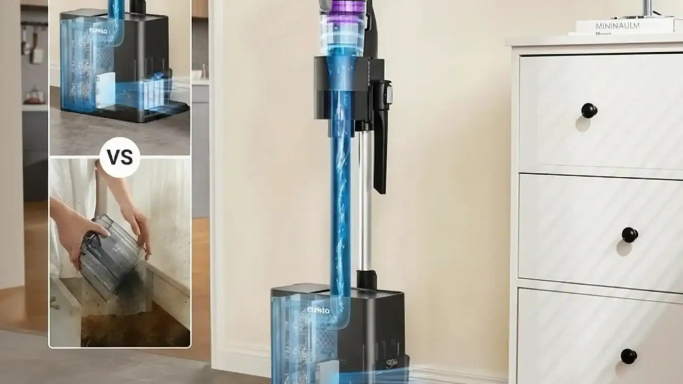
Escala tu Marca con Aspiradoras Domésticas Personalizadas de Alto Rendimiento

Propiedades de los Materiales para Entornos de Alta Temperatura
Los materiales de alta temperatura mantienen la integridad estructural y la resistencia a la oxidación por encima de 650 °C. Los ingenieros priorizan la baja expansión térmica y la resistencia a la fluencia lenta al 50 % del punto de fusión absoluto del material.
Fundamentos de la estabilidad y resistencia a altas temperaturas
Los materiales que operan por encima del 50 % de su punto de fusión absoluto requieren una alta resistencia a la oxidación y a la fluencia lenta. El acero inoxidable estándar falla bajo cargas dinámicas por encima de 600 °C, lo que hace necesarias las superaleaciones para la estabilidad estructural en esos rangos.
Ferrítico grados de acero inoxidable (4713 a 4762) manejan entornos de hasta 1150°C. Su aleación de cromo-silicio-aluminio previene la corrosión de metales fundidos y reduce los ataques de azufre. Estas aleaciones superan a los grados austeníticos en escenarios de choque térmico porque proporcionan menor expansión térmica y mayor conductividad térmica.
Especificaciones técnicas para aleaciones, cerámicas y polímeros
Los límites de aplicación específicos dictan la selección de materiales en función de los picos de temperatura y los requisitos de carga:
- Inconel 718 (base níquel): Mantiene una resistencia a la tracción de 540 MPa a 704°C; estándar para discos de turbina aeroespacial.
- Aleación TZM (base molibdeno): Ofrece una resistencia de 200 MPa a 1200°C con baja expansión térmica de 4.9×10⁻⁶/°C.
- Compuestos C/SiC: Temperatura máxima de 1650°C; conductividad térmica de 15 W/m·K para protección de naves espaciales.
- Fibras cerámicas Nextel: Resistentes al calor hasta 1300°C con una contracción inferior al 3% durante 15 horas.
- PEEK (Polímero): Uso continuo de 260°C y exposición a corto plazo de 300°C para componentes no metálicos.
- HA-31 (a base de cobalto): Tasas de oxidación inferiores a 0.1 mm/año a 980°C.
Pruebas de Seguridad y Protocolos de Control de Calidad
Validamos la estabilidad térmica utilizando los marcos IEC y MIL-STD. Nuestro protocolo de control de calidad de triple capa previene riesgos de quemaduras y fuga térmica de la batería mediante verificación de seguridad funcional 100% y pruebas de abuso térmico.
| Protocolo / Estándar | Aplicación principal | 13. Métrica Clave de Rendimiento |
|---|---|---|
| IEC 61010-1 | Prueba de aumento de temperatura | Ambiente de referencia de 40°C + aumento medido |
| MIL-STD-810H 501.7 | Estrés por alta temperatura | Procedimiento A (Exposición) y Procedimiento B (Operación) |
| ISO 6469-1 AMD 1 | Seguridad de baterías y vehículos eléctricos | Límites de abuso térmico y propagación de fuga térmica |
| MIL-STD-461F | Integridad electrónica | Cumplimiento de EMC para fuentes de alimentación de alta fiabilidad |
Normas internacionales de seguridad y evaluación de riesgos térmicos
Los ingenieros utilizan IEC 61010-1 e IEC 60950-1 para establecer límites de aumento de temperatura. Calculamos estos sumando el aumento de temperatura registrado a una temperatura ambiente de referencia de 40 °C. Esto garantiza que el hardware siga siendo seguro incluso en entornos de alto calor como el habitáculo de un vehículo en verano.
- Sondas de accesibilidad: Uso de sondas articuladas para adultos y niños para identificar riesgos de quemaduras en superficies de contacto según datos de NEISS.
- MIL-STD-810H 501.7: Validación de equipos bajo el Procedimiento A (exposición en almacenamiento) y el Procedimiento B (estabilidad operativa) en condiciones climáticas extremas.
- Modelado de termopares: Medición directa de temperaturas superficiales frente a límites de material derivados de la inercia térmica y la difusividad.
- Umbrales de placa base: Los módulos de alta potencia como el LCC600 deben funcionar a temperaturas de placa base de 85 °C sin reducción de potencia para superar la certificación industrial.
Protocolos de control de calidad industrial y validación de componentes especializados
La integridad de fabricación se basa en un ciclo de inspección de tres capas. Cada unidad se somete a una verificación funcional antes de salir de las instalaciones. Este proceso identifica defectos de componentes que podrían provocar fallos térmicos o caídas de eficiencia bajo carga.
- Control de calidad de tres capas: Implementación sistemática del Control de Calidad de Entrada (IQC), Control de Calidad de Proceso (PQC) y Control de Calidad Final (FQC).
- Pruebas de abuso térmico: Calentamiento rápido pruebas según ISO 6469-1 para evaluar bombas y cargadores de litio para riesgos de fuga térmica.
- Estándares JPL D-22011: Validación a nivel de sistema, incluyendo predicciones de peor caso en caliente/frío y verificaciones de integridad posteriores a las pruebas para hardware de misión crítica.
- Certificación de Terceros: Validación externa por SGS, Intertek o TUV Rheinland para confirmar el cumplimiento de CE, FCC y RoHS.
Para sistemas de 600W, el enfoque se centra en la fiabilidad con refrigeración por conducción. Estas unidades deben mantener una eficiencia superior al 90% mientras gestionan el calor mediante disipadores integrados o ventiladores de un solo riel. La adhesión estricta a los circuitos OTP (Protección por Sobretemperatura) garantiza que el dispositivo se apague antes de alcanzar puntos críticos de fallo, manteniendo un MTBF superior a 100,000 horas.
Reflexiones finales
Refrigerar 600W exige precisión, no conjeturas. Usar plásticos estándar sin considerar la Temperatura de Deflexión Térmica (HDT) garantiza fallos estructurales por fluencia a medida que las temperaturas internas aumentan.
Imponga un límite de 85°C y valídelo mediante CFD antes del prototipado. Sustituya los plásticos de baja HDT por PEEK o Nylon 66 reforzado para cualquier componente estructural cercano al riel de alimentación.
Preguntas frecuentes
¿Dónde están ubicadas las rejillas de ventilación en la carcasa para evitar soplar al usuario?
Los fabricantes colocan las rejillas de ventilación en los lados traseros o laterales de la carcasa, fuera de la zona de agarre. Esta disposición orienta el flujo de aire de enfriamiento lejos del mango para evitar que el aire golpee la mano o la cara del usuario durante el funcionamiento.
¿Los motores incluyen un corte térmico autorreiniciable (TCO)?
Sí. Los motores utilizan protectores autorreinicibles como la serie Klixon 15AM. Estos dispositivos se abren a temperaturas preestablecidas entre 65 y 170°C y se cierran automáticamente una vez que el motor se enfría, soportando un rango de resistencia de 300 a 10,000 ciclos, cumpliendo con los estándares IEC 60730.
¿Cuál es la temperatura máxima de la superficie del mango después de 10 minutos de funcionamiento?
Bajo la norma IEC 60335-1 normas de seguridad, las superficies del mango deben mantenerse por debajo de los umbrales de quemadura humana. Después de 10 minutos de funcionamiento continuo, las temperaturas del agarre suelen permanecer entre 48 y 60°C para garantizar un contacto seguro con la piel del usuario.

 English
  Español
  Français
  Deutsch
  Português do Brasil
  Русский
  한국어
한국어  日本語
日本語  العربية