跳转到主要内容 跳转到页脚
B2B procurement teams and product engineers face significant challenges when balancing raw power with operational efficiency in industrial vacuum systems. While high-wattage motors might signal capability, a 20 kPa vacuum rating—equivalent to roughly 80 inches of water lift—defines the actual force required to pull dense debris from heavy-duty surfaces. Reaching this performance benchmark requires high-speed brushless DC (BLDC) motors capable of 75,000 to 80,000 RPM, which provide the power density needed for compact robotic or cordless applications while avoiding the rapid wear associated with traditional carbon brushes.
This guide explores the engineering frameworks necessary to sustain peak suction, from optimizing cyclone geometry with specific 4D–6D height ratios to managing the non-linear energy costs of deeper vacuum levels. We break down motor technology selection, noise suppression techniques to keep operation below 75 dB(A), and the financial impact of utilizing premium materials like stainless steel 316. Understanding these technical benchmarks allows manufacturers to build systems that reduce the total cost of ownership by up to 20% through improved energy ROI and lifecycle maintenance.
Distinguishing Between KPA Suction and Airflow CFM
Vacuum performance relies on two distinct metrics: kPa measures the pressure difference or ‘lift’ needed to pull heavy debris from surfaces, while CFM measures the air volume required to transport that debris into the canister. Balancing these ensures a 20 kPa motor provides enough suction to move dirt without sacrificing the airflow needed for effective filtration.
Static Pressure vs. Volume Flow Rates
A 20 kPa rating equals roughly 80 inches of water lift. This benchmark defines high-performance vacuums capable of pulling dense debris from deep carpet fibers. While suction creates the initial lift, CFM (Cubic Feet per Minute) tracks the total air volume moving through the system. High-end consumer models typically range between 100 and 120 CFM to maintain optimal particle suspension during transport.
Suction provides the necessary velocity when the air path becomes restricted. In scenarios involving narrow crevice tools or systems with loaded filters, airflow naturally drops. The kPa rating ensures the motor maintains enough pressure to overcome these resistances and keep debris moving toward the collection canister.
Measuring Performance via the Airwatt Standard
Engineers use the ASTM F558-13 formula to calculate Airwatts, which represents the actual cleaning power. This calculation multiplies CFM by the inches of water lift and a constant factor of 0.117354. This integration shows that high suction alone cannot clean effectively without sufficient volume flow.
Designing a motor for 20 kPa suction often involves two-stage turbines. These components increase lift capabilities but can reduce total CFM if the motor housing lacks proper ventilation. Industrial applications for heavy materials like gravel or sand require a precise balance. High pressure prevents clogs in the hose, while a flow of 100+ CFM ensures the material reaches the canister without dropping out of the airstream.
Motor Technology Selection for Peak Performance
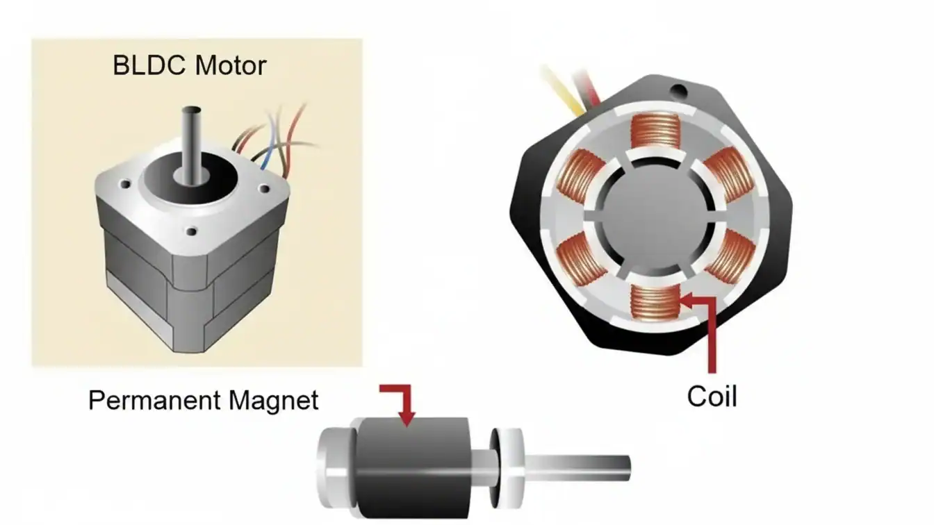
Achieving 20 kPa suction requires high-speed brushless DC (BLDC) motors capable of 75,000 to 80,000 RPM. These motors typically operate between 200W and 350W, offering the efficiency and power density necessary for compact, cordless, or robotic systems. Choosing BLDC over universal motors ensures longer lifecycles and better thermal management in high-demand cleaning applications.
| Motor Model Type | Electrical Specifications | Performance Output |
|---|---|---|
| BL55 High-Power BLDC | 350W | 25.2V DC | 80,000 RPM | 20 kPa |
| BL5550F Compact BLDC | 200W | 21.6V DC | 10A | 75,000 RPM | 20 kPa |
| Mains-Powered Universal | 220V AC | 50/60 Hz | 4.72″ Frame | 20 kPa |
Brushless DC Design for Compact High Suction
High-speed BLDC rotors reach speeds of 75,000 to 80,000 RPM to generate the negative pressure needed for 20 kPa systems. Electronic commutation and permanent-magnet rotors reduce mechanical wear and thermal loss compared to brushed universal motors. This design choice enables the motor to maintain peak suction without the rapid degradation associated with carbon brushes.
Frame diameters as small as 55mm allow these motors to fit within the constrained housing of cordless stick and robotic vacuums. Integrated controllers manage power distribution to provide adjustable suction levels, ranging from 2 kPa for light maintenance to a 20 kPa maximum mode. This versatility allows manufacturers to balance battery life with raw cleaning power in portable form factors.
Performance Benchmarks and Engineering Certifications
Standard 20 kPa configurations often utilize the BL55 model, which features 350W rated power and 25.2V DC input. System efficiency for motors in the 200W to 350W range typically falls between 46% and 65%. These units frequently carry an IE1 efficiency classification, balancing manufacturing costs with the operational demands of high-performance household appliances.
Continuous current draw for 21.6V systems averages 10A to sustain high-torque performance at 75,000 RPM. Engineers verify manufacturing quality through ISO 9001, ISO 14001, and IATF 16949 certifications. These standards ensure that every motor assembly meets the strict tolerances required for high-speed rotation and consistent vacuum pressure across global supply chains.
Optimizing Cyclone Geometry and Filtration Efficiency
High-efficiency cyclone design utilizes specific dimensionless ratios, typically maintaining a total height of 4D–6D and a vortex finder diameter of 0.40–0.50D. Engineers balance cutoff diameter (x50) against pressure drop, often allowing for a 1–4 kPa drop in 20 kPa systems to achieve significant mass loss reduction.
Dimensionless Ratios and Separation Mechanics
Technical literature identifies a narrow range of dimensionless geometry ratios that maximize separation performance. Reverse-flow cyclones typically use an inlet height (a) between 0.50D and 0.60D and an inlet width (b) of 0.20D to 0.25D, where D is the body diameter. These ratios provide sufficient swirl intensity while maintaining stable pressure levels. The vortex finder diameter (Dx), often set at 0.40D to 0.50D, and its length (S), ranging from 0.50D to 0.70D, regulate the residence time of particles within the primary vortex.
Designers anchor the total height (Ht) between 4D and 6D and set the cone tip diameter (Bc) at 0.375D to prevent re-entrainment. These dimensions minimize saltation, which occurs when air currents pull collected particles back into the exhaust stream. Optimization workflows treat seven variables—inlet height, width, vortex finder diameter, length, barrel height, total height, and cone tip diameter—as interconnected factors that determine the 50% collection efficiency cutoff diameter (x50) and pressure drop (ΔP).
Geometric Tuning for 20 kPa Suction Power
Vacuum systems with 20 kPa of suction head support pressure drop budgets between 1 kPa and 4 kPa, enabling higher filtration rates. Optimized RS_VHE geometries feature square inlets and cylindrical bodies roughly 50% taller than standard high-efficiency designs. Data from Advanced Cyclone Systems, S.A. indicates these modifications reduce mass loss by a factor of 2.3 when handling high-density materials like HDPE particles with densities around 860 kg/m³.
CFD-driven Kriging models show that vortex finder diameter and inlet width are the most sensitive variables for separation. Engineers use these models to explore Pareto-optimal trade-offs, ensuring the cyclone geometry exploits the 20 kPa suction limit to improve particle capture rather than simply dissipating energy. Validated configurations maintain performance even at the upper end of the pressure drop range, making them suitable for high-performance industrial and consumer vacuum applications where footprint and efficiency are equally prioritized.
Scale Your Brand with Premium OEM/ODM Home Vacuum Solutions

Balancing Energy Consumption with High Suction Output
Achieving 20 kPa suction involves managing a steep energy curve where vacuum depth and power draw are non-linearly linked. Efficiency depends on selecting two-stage pump systems, utilizing decentralized architectures to reduce line loss, and adhering to ISO 21360-2:2012 standards to optimize the air flow-to-kilowatt ratio.
The Non-Linear Energy Cost of Vacuum Depth
Industrial vacuum systems encounter physical limitations when pushing toward deeper suction levels. Data shows that raising vacuum from 60 kPa to 90 kPa gauge increases lifting force by 1.5 times, yet the energy requirement surges tenfold. This non-linear relationship makes 20 kPa absolute pressure a critical threshold for efficiency. For liquid ring pumps, this pressure represents a lower limit where pumping capacity begins to drop rapidly. Performance charts from manufacturers like Metal Bellows demonstrate that as suction depth increases, air throughput measured in liters per minute decreases. This relationship makes flow per kilowatt the primary metric for evaluating system performance and energy ROI.
Optimization Strategies and Performance Standards
Standardization provides a clear path for benchmarking energy versus suction performance. ISO 21360-2:2012 defines the methods for measuring volume flow rate and power consumption across various pump types. Engineers can increase efficiency by 35% to 40% by selecting two-stage pump configurations instead of single-stage units when operating at 20 kPa levels. System architecture also impacts the total energy footprint. Shifting from centralized vacuum plants to decentralized, localized setups can reduce annual energy use from 1656 kWh to 17 kWh by minimizing line losses and pressure drops. Modern control systems further enhance these results. Variable-speed drives and automatic shut-off controls allow motors to cycle based on real-time demand, which often reduces energy consumption by up to 26% while maintaining target suction levels.

Noise Reduction Strategies for High Power Motors
Engineers achieve quiet 20 kPa suction by transitioning from brushed to brushless motors and using acoustic insulation to keep noise levels under 75 dB(A). Modern designs incorporate multi-chamber bodies and vibration isolation to meet ASA/ANSI S12.3-2023 standards, ensuring industrial power does not exceed the 85 dB(A) hearing-protection threshold.
Acoustic Benchmarks and Regulatory Standards for 2026
Modern industrial vacuums target noise levels below 70–75 dB(A) at the operator position to improve safety and user comfort. Premium 20 kPa units utilize ASA/ANSI S12.3-2023 frameworks to declare A-weighted sound power levels, allowing for transparent performance comparisons across different equipment batches. Reducing noise below the 85 dB(A) threshold eliminates the legal requirement for operator hearing protection in most industrial jurisdictions, simplifying compliance. Benchmarking against extremely quiet consumer models shows that 68–72 dB(A) is achievable even at high airflow duty points through optimized housing design.
Mechanical and Airflow Engineering for Sound Suppression
Brushless motors eliminate mechanical commutation noise, significantly reducing high-frequency tonal output compared to legacy brushed designs. Acoustically lined motor chambers and multi-chamber bodies use baffled ducts to break up sound waves and reduce turbulence-generated noise throughout the air path. Vibration-isolating mounts decouple the high-speed fan and motor from the main housing to prevent structure-borne noise resonance in the outer casing. Variable-speed drives and inverter controls allow the system to drop RPM when full 20 kPa suction is unnecessary, keeping operation in the quiet 68 dB(A) range during standard duty cycles.
Sustaining Peak KPA Over the Product Lifecycle
Engineers sustain 20 kPa vacuum performance by positioning the setpoint within the pump’s ideal efficiency window (typically 20–100 kPa absolute) rather than at its physical limit. Long-term stability depends on using corrosion-resistant alloys, anti-cavitation hardware, and high-fatigue-strength components to prevent the gradual downward shift of vacuum-vs-airflow curves caused by seal and impeller wear.
| Pump Technology | Ideal 20 kPa Stability Range | Lifecycle Maintenance Strategy |
|---|---|---|
| Two-Stage Liquid Ring | 20–100 kPa Absolute | Titanium wetted parts & anti-cavitation devices |
| Industrial Roots Blower | -20 kPa Gauge (Continuous) | Maintain 50% ultimate vacuum capability margin |
| Pneumatic Venturi | ~33 kPa Absolute (68 kPa Differential) | 80 psi supply air to offset nozzle orifice wear |
| Lab Diaphragm/Bellows | 20–30 kPa Differential | Thermal management for 2.8W low-power density |
Vacuum Stability Thresholds and Mechanical Wear Mechanisms
20 kPa serves as a practical lower bound for stable long-term operation. Dropping below this point causes rapid losses in pumping capacity for single-stage designs. Component wear in seals, bellows, and impellers creates a direct downward shift in the vacuum-vs-airflow curve. This degradation requires higher motor RPM to maintain original kPa levels. Continuous duty cycles at 20-30 kPa differential generate specific heat loads that require active thermal management. Heat loads can cause elasticity loss in diaphragms and gaskets, leading to vacuum leaks. Performance data from metal bellows pumps indicates that maintaining 20 kPa at a specific LPM becomes more energy-intensive as component fatigue reduces volumetric efficiency.
Engineering Strategies for Continuous Performance and Reliability
Selecting stainless steel, duplex steel, or titanium for wetted parts prevents corrosive and erosive wear. This wear typically thins impeller blades and expands internal clearances. Implementation of anti-cavitation devices and double mechanical seals preserves the internal geometry required for high-efficiency vacuum generation. Using a 20 kPa setpoint as a routine conveying level—rather than an ultimate vacuum limit—provides a performance margin that accommodates minor component wear without system failure. Low power density baselines, such as 2.8W for 3 L/min at 20–30 kPa, provide benchmarks for energy-efficient operation. These benchmarks minimize heat-related seal failure over the product lifecycle and ensure the pump operates within its intended efficiency window.
Bill of Materials Cost Analysis for High Performance Units
High-performance units costing between $5,000 and $12,000 utilize premium materials like stainless steel 316 and PTFE coatings. While advanced components like brushless DC motors and oil-free pump designs increase the initial bill of materials by 20-30%, they lower the total cost of ownership by reducing energy consumption by up to 20%.
Material Grade and Pump Technology Drivers
Manufacturing high-performance vacuum systems requires a shift from standard aluminum alloy to chemically resistant materials. Premium units integrate stainless steel 316 and PTFE-coated surfaces to withstand aggressive environments, whereas entry-level models often use aluminum alloy casings. While aluminum reduces initial costs by 30%, these units typically reach their end of life within 18 to 24 months when exposed to corrosive gases.
Pump technology accounts for a significant portion of the price variance. Oil-free diaphragm and scroll pump designs command a 20-30% premium over oil-sealed alternatives. This increase stems from the requirement for specialized self-lubricating bearings and tighter precision tolerances during machining. Systems delivering vacuum levels below 5 mbar and flow rates of 15-30 L/min utilize specialized internal seals that push the total unit price into the $5,000 to $12,000 range.
Compliance with global quality frameworks like ISO 9001 and IATF 16949 influences the bill of materials. These standards ensure component reliability but add roughly 5-8% to the manufacturing overhead for high-suction units.
Operational Efficiency and Lifecycle Expense Breakdown
Financial assessments of vacuum systems often focus on the initial purchase, yet this only represents 10% of the lifetime cost. Total cost of ownership models indicate that energy consumption drives 50% of the long-term expense, while ongoing maintenance accounts for 30%. Selecting components with higher upfront costs results in lower cumulative spending over the equipment’s lifespan.
Brushless DC motors provide a clear example of this economic trade-off. These motors generate 15-20% energy savings over a five-year period compared to the brushed motors found in cheaper alternatives. These efficiencies become critical as raw material costs for high-grade steel and rubber seals are projected to rise by 8-12% by 2026, making durable, energy-efficient designs essential for long-term budget stability.
Modular designs in high-performance units facilitate targeted part replacement. Repairing an aging oil-sealed pump frequently costs more than 60% of the price of a new unit. Investing in modular systems allows facilities to replace specific wear components rather than the entire motor or pump assembly, extending the operational life of the equipment beyond a decade.
Final Thoughts
Designing for 20 kPa suction requires a technical balance between static pressure and airflow volume. Successful systems use high-speed brushless motors and optimized cyclone geometry to maintain lift while preventing debris clogs. This approach ensures the vacuum performs effectively under heavy loads and across different surfaces.
Long-term reliability depends on choosing durable materials and efficient pump architectures that minimize energy waste. Investing in modular designs and high-grade components reduces the total cost of ownership by lowering maintenance needs. Focusing on these engineering details allows manufacturers to deliver high-performance tools that meet industrial standards and user expectations.
Frequently Asked Questions
What does KPA represent in vacuum cleaner specifications?
KPA (kilopascals) measures suction pressure, with 1 KPA equaling 1,000 Pascals (Pa). It quantifies the vacuum’s ability to lift debris against gravity and resistance, serving as a primary indicator of motor strength.
Is 20 KPA considered strong suction for a portable vacuum?
A 20 KPA rating indicates high-end suction performance for 2026 models. Since standard portable vacuums usually operate between 2-3 KPA and high-suction units typically start at 5 KPA, 20 KPA provides the force needed to clean dense carpets and heavy particles effectively.
Can I convert Airwatts directly into KPA?
No direct conversion formula exists because they measure different properties. Airwatts (AW) calculates the combination of airflow (CFM) and water lift, while KPA strictly measures suction pressure. Both metrics are used to evaluate performance but cannot be swapped mathematically.
Does a higher wattage motor guarantee more suction?
Motor wattage measures electrical power consumption rather than cleaning efficiency. Actual suction power depends on motor design, internal seal quality, and airflow geometry. An efficient motor can produce 20 KPA with lower wattage than a poorly designed high-wattage alternative.
Why does a vacuum lose suction power during use?
Suction loss generally occurs when HEPA filters become clogged or dust containers fill up, which increases air resistance. Regular maintenance and ensuring seals remain airtight are necessary to sustain the rated KPA over the product lifecycle.
How do manufacturers officially test vacuum suction power?
Suction is typically tested under standardized conditions using water lift (sealed suction) or KPA sensors. Tests are conducted with empty filters and bags to establish the peak performance rating before any debris-related resistance occurs.