 跳转到主要内容 跳转到页脚
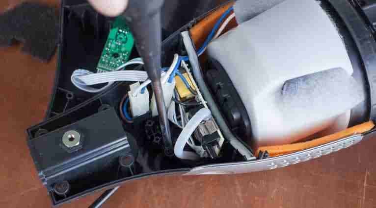
Facility managers and engineers face constant pressure to maintain water hygiene while reducing equipment downtime. Standard steel tanks often suffer from internal corrosion and frequent pump cycling because they lack a physical barrier between air and water. Dual-tank systems solve these issues by isolating clean and waste reservoirs, which prevents cross-contamination and stabilizes system pressure for long-term reliability.
This analysis details the engineering standards for reliable pressure systems, focusing on the durability of butyl rubber bladders and virgin ABS resin. We evaluate the 1:1 gallon-to-room capacity ratio and the load requirements for gaskets like EPDM or PTFE. The following sections also outline ergonomic protocols that limit manual lifts to 30 pounds to ensure operational efficiency without risking musculoskeletal strain.
The “Bladder” vs. “Tank-in-Tank” Design
Bladder tanks utilize a flexible butyl rubber barrier to separate water from air, preventing internal corrosion and maintaining pressure stability. Tank-in-tank designs lack this barrier, exposing metal to water and requiring manual air volume adjustments via sight glasses to prevent frequent pump cycling.
| Design Feature | Bladder Tank System | Tank-in-Tank (Plain Steel) |
|---|---|---|
| Air/Water Separation | Replaceable Butyl Rubber Bladder | Direct Contact (None) |
| Corrosion Risk | Minimal; barrier isolates water | High; oxidation on shell interior |
| Maintenance Needs | Pre-charge pressure monitoring | Manual air recharge via sight glass |
Mechanisms of Air and Water Separation
Replaceable butyl rubber bladders prevent oxygen-driven corrosion by eliminating contact between water and the carbon steel vessel. These systems isolate the liquid within a flexible membrane, ensuring the air charge remains stable over several years of operation. By preventing air from dissolving into the water supply, the design maintains a consistent pressure cushion that protects the pump and piping infrastructure.
Tank-in-tank systems operate using a plain steel vessel where water and air occupy the same space. These configurations require an air fill valve and a sight glass to maintain a 50/50 air-to-water ratio at ambient pressure. Without a physical barrier, the water absorbs the air over time, which reduces the cushion volume and leads to rapid pump cycling. Flexible bladders avoid this problem by compressing to the maximum system operating pressure (P_MAX) to absorb thermal expansion without requiring manual intervention.

Pressure Integrity and Material Specifications
ASME Section VIII, Division I compliance supports a Maximum Allowable Working Pressure (MAWP) of 175 psi or 12.1 bar for modern bladder vessels. Grit-blasted epoxy-coated interiors protect the shells from moisture, while 1-inch bronze ball valves ensure corrosion-resistant flow control at connection points. These specifications ensure the tank can withstand high-pressure fluctuations in hydronic and well-water applications.
Advanced system infrastructure uses Schedule 40 ASTM B-43 piping and perforated PVC center tubes to manage high-volume drawdown cycles. The center tubes prevent the bladder from folding or blocking the outlet, which is a common failure point in lower-quality designs. These material standards define the long-term durability of 2026 pressure systems, providing a more reliable alternative to legacy plain steel tanks that lack internal coatings or structural reinforcement.
Capacity Math: 1 Gallon = 1 Room
The 2026 efficiency benchmark for dual-tank systems uses a 1:1 gallon-to-room ratio, assuming a standard 150-square-foot coverage area. This calculation factors in a 90% usable volume limit to prevent overflow while maintaining a density load of 8.34 lbs per gallon for ergonomic stability.
The Coverage Benchmark for Cleaning Systems
Modern 2026 utility standards designate one gallon of fluid as the baseline for treating a single 150-square-foot interior space. This ratio ensures that maintenance cycles align with standard architectural room sizes, allowing for predictable replenishment schedules. Engineers subtract a 10% buffer from the total internal volume to establish a 90% usable capacity, which prevents suction loss or dead volume issues at the bottom of the reservoir.
Dual-tank configurations separate clean and waste reservoirs to maintain this 1:1 ratio without cross-contamination. By isolating the fluid streams, the system ensures that the chemical concentration remains effective across the entire 150-square-foot zone. This separation also aids in weight distribution, as the shifting mass between tanks must remain centered to prevent equipment instability during movement.
Load Calculations and Structural Integrity
Structural designers use a water density of 8.34 lbs/gal to calculate foundation loads and handle-stress limits for portable units. When tanks reach maximum capacity, the equipment must withstand significant kinetic energy during transport. API 650 standards for carbon steel and API 620 for specialized storage guide the shell thickness requirements, ensuring the material can resist hydrostatic pressure without deforming or leaking over time.
OIML R 85:2008 tank gauging standards provide the precision needed for Tank Capacity Tables (TCT). These tables allow operators to track available headspace accurately, which is vital for maintaining the 90% fill limit. Using these rigorous engineering benchmarks ensures that dual-tank systems remain functional and safe, even when operating at the edge of their volume specifications.
Filling & Emptying: Ergonomics of Heavy Water
Safe water handling requires limiting container weight to 30 pounds and maintaining lift heights between 30 and 40 inches. Proper ergonomic design utilizes electric pallet jacks for multi-rack transport and limits batch sizes to six bottles on adjustable scissor lifts to minimize physical strain.
| Handling Task | Safety Threshold | Equipment & Protocol |
|---|---|---|
| DI Water Containers (>3 gal) | 30 lbs Maximum | Marked half-fill lines & hoses |
| Vertical Transfer Range | 30–40 Inches | Step stools, catwalks, & platforms |
| Batch Bottle Transfers | 6 Bottle Limit | Height-adjustable scissor lift |
| Bulk Rack Delivery | 3 Racks Maximum | Electric pallet jack (2-man team) |
Weight Thresholds and Manual Handling Protocols
Safety protocols restrict high-purity de-ionized water containers over 3 gallons to a 30-pound maximum weight. Maintaining this limit protects the musculoskeletal system during the high-frequency movements common in dual-system environments. Facilities use marked half-fill lines on buckets and utilize hoses for filling to prevent the heavy pouring and tipping that often leads to overexertion. Operators keep containers close to the torso during every lift to reduce spinal load and improve core stability. If a container exceeds the weight limit, teams must use a two-person lift to distribute the load until the site installs permanent mechanical assistance.
Industrial Lifting Heights and Mechanical Assistance
Industrial design standards set all lift and lower actions for water containers between 30 and 40 inches from the standing surface. Personnel use step stools, platforms, or catwalks to ensure work stays within this optimal power zone. For batch transfers, workers limit loads to six bottles per height-adjustable scissor lift to stay within safe mechanical operating limits and avoid manual truck loading. Heavy storage rack deliveries require electric pallet jacks and function strictly as two-man operations. These mechanical aids and height requirements significantly reduce back strain and improve the efficiency of filling and emptying cycles in professional water management systems.
Scale Your Brand with High-Performance Home Vacuum Solutions

Gasket Quality: Preventing Leaks at the Connection
Quality seals depend on selecting resilient materials like EPDM or PTFE and applying precise bolt loads between 50% and 100% of yield strength. These components must pass ASTM F36 compressibility tests to ensure they maintain a residual load higher than the 4.4 bar internal working pressure found in 2026 tank designs.
Material Resilience and Sealing Mechanics
Manufacturers use 1/4-inch EPDM gaskets for secondary containment to bridge surface irregularities in PVC and polyethylene flanges. These materials provide the necessary flexibility to fill gaps caused by non-parallel faces or flange distortions common in plastic tank systems. By choosing materials that conform to the specific texture of the flange, operators reduce the risk of bypass leaks during fluid transfer.
PTFE-enveloped gaskets featuring a 0.5mm thickness offer essential chemical resistance and thermal stability for operations reaching 250°C. These gaskets often include a resilient core to maintain pressure. Non-metallic seals rely on friction generated by compressive loads to resist internal fluid pressure and prevent lateral extrusion, which could lead to a sudden blowout.
Specific seal geometries, such as 14mm x 14mm sections for hatch connections, ensure surface contact remains consistent across the entire diameter. Engineering teams also deploy dust cap seals between 2mm and 3mm thick to protect secondary entry points. Maintaining these precise dimensions prevents the gasket from shifting under the 0-200 psi pressures monitored in modern seal support systems.
Bolt Load Calculations and Testing Standards
Optimal sealing requires bolt loads between 50% and 100% of the yield strength to maintain residual stress under cyclic loads. This tension ensures the joint remains tight as the gasket material relaxes or the system undergoes thermal expansion. Most double-wall polyethylene tanks use a minimum of four 1/2-inch bolts to secure the outside tank wall and maintain this required force.
The ASTM F36 standard validates compressibility and recovery rates for all sealing components. This verification ensures the gasket conforms to the flange without sustaining permanent damage. Proper conformability allows the material to spring back during pressure drops, ensuring the seal stays intact throughout the service life of the connection.
Systems must withstand a working pressure of 4.4 bar and pass safety tests at 6.0 bar to meet 2026 containment benchmarks. Engineering teams use EN 1591-1 calculations to account for assembly tolerances and prevent under-loading during installation. Following these rigorous standards ensures that the residual load always exceeds the internal working pressure, preventing hazardous leaks in industrial environments.
Material Sourcing: Mold-Resistant ABS Tanks
Sourcing for dual-tank systems prioritizes virgin ABS resin over recycled materials to prevent bacterial growth and structural fatigue. Manufacturers achieve durability by maintaining a minimum wall thickness of 0.187 inches and managing injection molding parameters, such as 0.5% shrinkage and 50-70 MPa pressure, to ensure airtight seals.
Antimicrobial Properties and Resin Purity Standards
Manufacturers select virgin ABS resin and prohibit the use of regrind or recycled materials to ensure water tanks meet ASTM D 1998-97 hygiene standards. This high degree of purity prevents the structural fatigue and bacterial colonization often associated with lower-grade or contaminated plastics. Integrating UV stabilizers with a “15” rating provides 50% protection after 15,000 hours of light exposure, which effectively halts material degradation in various environments. Engineering teams analyze chemical resistance charts to verify that the chosen resin withstands common cleaning agents without leaching chemicals or suffering surface pitting. Prioritizing high-impact ABS with a 60% gel minimum ensures the dual-tank system maintains structural stability even in high-humidity conditions.
Injection Molding Parameters and Structural Tolerances
Technicians control barrel temperatures between 180-230°C and maintain injection pressures of 50-70 MPa to achieve uniform wall density across the entire tank component. The manufacturing process preserves a minimum wall thickness of 0.187 inches (3/16 inch) across the shell and heads to prevent structural collapse or deformation during operation. Managing a tight shrinkage tolerance of 0.5% ensures the finished tank fits precisely into the appliance housing, maintaining the alignment necessary for leak-proof performance. Quality control protocols enforce a strict ±20% wall thickness tolerance, verifying that no individual low area exceeds one square foot or compromises the integrity of the critical seal connections.
Final Thoughts
Choosing between bladder and tank-in-tank designs comes down to long-term maintenance goals. Bladder tanks stop rust and pressure loss by keeping air and water separate through a flexible barrier. In cleaning applications, dual-tank setups maintain hygiene by isolating fresh and dirty fluids, which ensures consistent chemical performance. Using high-quality virgin ABS resin and tested gaskets prevents the leaks and bacterial growth that often damage lower-grade equipment.
Following strict weight limits and lift heights keeps workers safe during daily water transfers. Engineering standards like ASME and ASTM provide the necessary framework for reliable performance in high-pressure environments. When manufacturers prioritize pure materials and precise seal loads, they create tools that handle heavy-duty tasks without failing. These technical choices define the efficiency and safety of modern water management systems.
Frequently Asked Questions
Can I remove the dirty water tank for manual cleaning?
Most dual-tank systems use a lift-off, fully removable recovery reservoir. This allows you to rinse the tank directly and remove debris easily, which prevents mold growth and bad smells.
What is the actual liquid capacity before the auto-shutoff engages?
Consumer-grade recovery tanks typically offer a working capacity between 0.5 and 1.0 gallon (1.9–3.8 L). An internal float valve shuts off suction once the liquid reaches this limit to keep the motor dry.
How do manufacturers test the seals for potential leaks?
While consumer units lack a universal 24-hour static test standard, high-quality tanks often meet industrial benchmarks like AWWA D100 or UL-142. They undergo hydrostatic testing at 1.3 to 1.5 times the service pressure to confirm the seals hold under stress.

 English
  Español
  Français
  Deutsch
  Português do Brasil
  Русский
  한국어
한국어  日本語
日本語  العربية