 跳转到主要内容 跳转到页脚

Persistent debris and fiber entanglement can stall industrial systems and drive up energy costs. Reliability in these environments depends on proactive engineering that manages material flow without constant human intervention. We focus on the design principles and hardware logic that prevent blockages and maintain suction power under heavy loads.
This analysis covers the fluid dynamics of air path geometry, where 90° bends cause significant deceleration compared to straight-line ducts with a loss coefficient of 0.9. We examine automated recovery systems that detect current spikes exceeding 400% of full load amps to trigger self-clearing cycles. Additionally, we review durability standards for filtration media, including ASTM D-6241 compliance for puncture resistance up to 558 lbs.

The “Sock Test”: Clearing Large Debris
The sock test utilizes woven polymer or HDPE netting filled with specialized media to block large debris while sustaining high flow rates. These systems capture 97-99% of total suspended solids and adhere to ASTM D-6241 standards for puncture resistance, ensuring structural integrity under heavy loads of up to 558 lbs.
Functional Principles of Sediment and Trash Capture
Woven polymer and geotextile casings act as check dams to isolate large trash, hydrocarbons, and sediment. HDPE filament netting with 3/8-inch openings permits water flow while blocking solids effectively. System designs achieve 97-99% capture of total suspended solids (TSS) during large-scale debris clearing. Self-weighting media ranging from 30 to 66 lbs ensures the barrier conforms to uneven surfaces without bypass.
Technical Performance and Durability Benchmarks
ASTM D-6241 compliance requires 558 lbs of puncture resistance to handle sharp or heavy debris. Filter socks maintain a flow capacity of 5 gpm/ft² while managing concentrated flow paths up to 1 cfs. An Apparent Opening Size (AOS) of 0.425mm (30 US Sieve) prevents fine sediment from clogging the primary intake. Standard dimensions of 9 to 10 feet in length provide sufficient surface area for high-volume debris filtration.
Air Path Geometry: Straight Lines vs. 90° Bends
Straight air paths maximize efficiency by reducing friction and maintaining particle velocity, while 90° bends introduce a pressure drop coefficient (K) of 0.9. These bends often cause energy loss and material impact damage, requiring higher power input to prevent debris from settling and creating clogs.
| Geometry Feature | Straight Air Path | 90° Mitre Bend |
|---|---|---|
| Loss Coefficient (K) | Negligible (~0.0) | 0.9 (Re 500-60,000) |
| Particle Velocity | Maintains peak speed | Significant deceleration |
| Energy Consumption | Optimized/Lower demand | Higher (High friction) |
| Maintenance Risk | Low clogging risk | High settling/abrasion |
Fluid Dynamics and Suction Efficiency
Straight-line ducts minimize particle-wall impacts, allowing debris to travel at peak velocity directly into the collection chamber. This layout preserves kinetic energy and prevents the premature drop-out of heavier materials. In contrast, 90° elbows cause significant speed loss, forcing the motor to consume more power to move the same volume of air. This efficiency gap becomes critical in battery-operated systems where every watt influences runtime.
Smooth internal geometries also reduce the scraping time of abrasive particles against the duct walls. Sharp angles create turbulence that traps debris against the surface longer than straight paths. Engineering teams prioritize 45° transitions over sharp 90° mitre bends to maintain consistent suction. These shallower angles provide a better balance between compact tool dimensions and high aerodynamic performance.
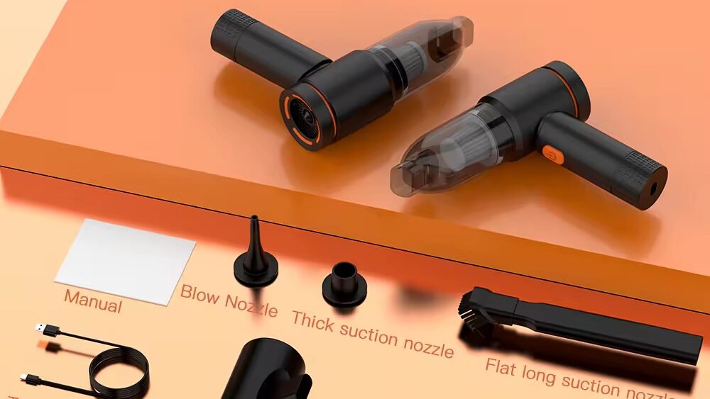
Pressure Drop and Clog Metrics
Sharp-edged 90° mitre elbows produce a consistent loss coefficient of K=0.9 across Reynolds numbers ranging from 500 to 60,000. Designers use this specific data to calculate the equivalent length of straight pipe required to match the pressure drop of a single bend. Precise modeling ensures the pump maintains enough static pressure to overcome the resistance of internal turns without stalling.
Two-phase flows involving air mixed with moisture create additional risks at 90° bends, including reverse flow and bubble fragmentation. This disruption often leads to wet clogs as moisture separates and traps dust at the apex of the turn. High-suction units reaching 20,000Pa utilize straight-path engineering to eliminate the 3% impedance deviations typically found in congested internal architectures, ensuring airflow remains stable under heavy loads.
Auto-Reverse: Motor Logic to Clear Jams
Auto-reverse logic uses solid-state relays to detect current spikes exceeding 400% of full load amps. When a jam occurs, Trip Class J settings trigger a shutdown within 2 seconds. The system then executes three to four automated reverse-run cycles to dislodge debris without manual intervention, maintaining 2026 performance standards.
| System Component | Detection Parameter | Clearing Logic |
|---|---|---|
| Motor Logic® Plus II | >400% FLA (2s Duration) | Trips 1 minute after startup to allow stabilization. |
| ConveyLinx-Ai2 | Sensor-Based Jam Detection | 3 successive reverse-run attempts per zone. |
| Rockwell E100 Relay | Current-Based (0.1 – 800A) | Selectable Trip Classes (10, 15, 20, 30). |
Overcurrent Monitoring and Trip Class J Protection
Solid-state overload relays like the Motor Logic® Plus II activate jam protection exactly 1 minute after motor startup. This delay prevents nuisance tripping during the initial inrush of current. The system triggers a trip when current levels exceed 400% of the full load amps (FLA) for a duration of 2 seconds. This rapid response protects the motor against mechanical seizing and structural stress.
Trip Class J configurations specifically handle high-torque stalled conditions to prevent winding damage. These settings offer a specialized response compared to standard thermal overloads. Adjustable trip classes, including 10, 15, 20, and 30, allow the relay to accommodate various motor inertia levels and specific acceleration times. Rockwell E100 modules integrate current-based protection across a range of 0.1 to 800A to ensure precise fault discrimination for complex conveyor networks.
Automated Recovery Cycles and Bidirectional Clearing
ConveyLinx-Ai2 logic executes 3 successive reverse-run attempts to clear sensor-detected jams automatically. If the obstruction persists, the system halts to prevent equipment wear. Control programs allow up to 4 restart attempts after an undercurrent fault before requiring a manual reset. Auto-reset timers typically engage after a 1-minute run time to ensure the motor has cooled sufficiently following a high-heat event.
DIP-switchable configurations in Eaton C306 relays enable phase loss and imbalance protection alongside jam recovery functions. This hardware-level logic provides a secondary layer of safety. Single-phase motor setups often disable reverse phase protection to allow the bidirectional movement necessary for clearing intake paths. By automating these sequences, facilities reduce the need for manual intervention and maintain continuous material flow in high-volume environments.
Scale Your Brand with Custom High-Performance Vacuum Cleaners

Access Hatches: User-Serviceable Ducts
Access hatches provide dedicated entry points for manual debris removal and internal duct inspection. These components ensure systems meet 2026 safety standards like NFPA 96 by allowing technicians to clear grease or dust buildup every 12 feet without dismantling the entire ventilation structure.
Maintenance Accessibility and Safety Protocols
Technicians follow NFPA 96 regulations which mandate access ports every 12 feet and at every change in duct direction. This placement facilitates cleaning to bare metal, which prevents fire hazards in commercial kitchens and industrial sites. Cam-lock mechanisms and integrated hardware allow for tool-free operation, speeding up routine inspections in high-clog environments. For installation, designers select tabbed frames for rectangular flat ducts or curved doors for circular configurations to ensure a flush, aerodynamic fit. Self-adhesive templates simplify the process of adding new hatches into 2026 ventilation systems without requiring complex measurements.
Material Engineering and Airtight Sealing Standards
Manufacturers utilize Z275G galvanised steel and 316 stainless steel to provide corrosion resistance against moisture and harsh chemical cleaners. These materials ensure longevity in demanding environments where humidity or grease concentrations are high. Airtight seals comply with BS EN15727:2010 and BESA DW144 standards, meaning installers do not need additional sealants or fixings after the initial setup. Dual-layer closed-cell neoprene gaskets maintain system integrity under pressure ratings reaching 2000Pa or 3” W.G. in both positive and negative environments. High-temperature variants exceed UL fire ratings with resistance up to 2300°F for specialized exhaust applications.
Transparent Trapdoors: Visualizing the Jam
Transparent trapdoor systems allow engineers to observe active arching and granular clogging in real-time. By utilizing high-transparency plexiglass containers and Particle Image Velocimetry (PIV), R&D teams monitor shear band propagation and displacement fields to optimize duct geometry against material jams.
Optical Analysis of Active Arching Mechanisms
Engineers use high-transparency plexiglass containers measuring 700 mm x 300 mm x 700 mm to study internal material flow while minimizing boundary friction. A Particle Image Velocimetry (PIV) system acquires data at 2 Hz, mapping surface settlement and horizontal shifts within the granular medium. CCD cameras aligned parallel to the trapdoor axis capture the evolution of active regions during the subsidence process.
This visualization of displacement fields identifies the transition from passive arching to full active region expansion. Monitoring these active regions provides a clear view of how materials behave under stress, allowing for precise adjustments to prevent clogging in industrial bulk material handling systems.
Shear Band Propagation and Displacement Metrics
Testing involves constant downward displacement speeds of 2.0 mm/min to simulate the gradual subsidence that leads to blockages. Critical displacement markers, denoted as Δ_cri, identify the exact point of minimum load mobilization on the trapdoor. Shear bands propagate through dilatancy, where volumetric dilation increases alongside surface settlement levels.
Vorticity measurements quantify micro-rotations in sheared zones, helping validate anti-clogging engineering models. Embedment ratios ranging from 1 to 4 determine how buried depth influences rigid block motion and arching strength in the system. These metrics define the physical limits of the material and guide the design of industrial storage and transport equipment.
Final Thoughts
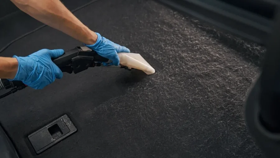
Reliable debris management comes down to a balance between smart geometry and responsive electronics. Systems that prioritize straight air paths maintain higher particle velocity and use less power, while auto-reverse logic provides a necessary safeguard to clear jams before they cause mechanical stress. Using these engineering strategies helps equipment handle everything from fine sediment to heavy pet hair without constant manual oversight.
Transparent trapdoors and quick-access hatches turn maintenance into a straightforward task rather than a complex teardown. These features allow operators to monitor flow in real-time and address obstructions immediately. Adopting these service-focused designs reduces repair costs and keeps systems running longer in demanding, high-volume environments.
Frequently Asked Questions
Do vacuum base stations require tool-free access hatches and minimal-bend air paths?
Industry standards for 2026 do not mandate these features as universal requirements. Engineers prioritize accessible maintenance designs and smooth piping transitions to minimize pressure drop and prevent debris accumulation during operation.
How do systems automatically manage potential clogs without motor reversal?
Many systems implement pulse jet automatic filter cleaning rather than motor reversal sequences. Technical efficiency relies on using larger diameter pipes and gradual bends to maintain high airflow and reduce the likelihood of jams in the conveying lines.

 English
  Español
  Français
  Deutsch
  Português do Brasil
  Русский
  한국어
한국어  日本語
日本語  العربية