 跳转到主要内容 跳转到页脚

B2B buyers often face significant risks when transitioning from a vacuum cleaner prototype to mass production. Inconsistent surface finishes or internal components that fail to meet safety standards can lead to costly delays and brand damage. Establishing a rigorous inspection process ensures that every sample matches the original engineering specifications before you commit to a full purchase order.
This guide outlines the critical steps for evaluating samples, ranging from aesthetic grading to functional stress tests. We cover precise metrics such as maintaining a Delta E limit of 2.00 for color accuracy and verifying suction pressure between 13,000Pa and 20,000Pa. The following sections also detail teardown requirements for 12 AWG copper wiring and the implementation of golden samples to calibrate long-term quality control.
Aesthetic Inspection
Aesthetic inspection categorizes surfaces into three classes (A, B, and C) based on visibility. We evaluate samples under 80-120 foot-candles of light, checking for scratches under 0.005 inches and color deviations within a Delta E limit of 2.00 to ensure consistency with the golden sample.
Surface Classifications and Viewing Standards
Inspectors divide components into Class A, Class B, and Class C zones to establish strictness levels based on final assembly visibility. Class A surfaces are those normally visible to the user, Class B surfaces are visible only with effort, and Class C surfaces remain hidden or require disassembly to see. For transparent or fluid-contact parts, we use high-polish SPI-B1 or SPI-B2 surface grades to ensure clarity. This systematic grading focuses quality control efforts on the most prominent areas of car accessories and electronics.
Controlled environmental settings minimize subjective errors during visual evaluation. Viewing conditions must stay between 80 and 120 foot-candles of white fluorescent light. Distance from the surface also changes by class: 18 inches for Class A, 24 inches for Class B, and 30 inches for Class C. Technicians apply rapid scan times of 1 to 2 seconds for areas under 4 square inches, allowing for an efficient search for prominent surface flaws without over-inspecting minor variations.
Quantitative Defect Limits and Finish Testing
Measurable tolerances define the limits for physical defects and color accuracy. Class A painted surfaces restrict defects to 0.010 inches, and any single flaw exceeding 0.020 inches triggers an immediate rejection. Raw material scratches must not exceed a width of 0.005 inches to prevent visible marring on finished housings. We enforce a strict color tolerance with a Delta E limit of 2.00, using digital spectrophotometry or direct comparison against a golden sample to maintain visual consistency across production batches.
Durability testing ensures the finish remains intact throughout the product life cycle. Inspectors verify coating adhesion by pulling Scotch 610 tape at a 90-degree angle; zero finish removal is acceptable. While Class A surfaces demand near-perfection, Class C surfaces allow for 4 to 6 minor defects per 16 square inches, as these areas are generally not seen during standard operation. These quantified metrics provide an objective framework for accepting or rejecting components based on their intended placement and use.

Fitment Check (Latches/Seals)
Fitment verification centers on measuring gasket compression levels and hardware alignment to meet IP65–IP67 or NEMA standards. Key metrics include verifying dimensional tolerances within ±0.25 mm and ensuring latch cam travel matches frame gaps to prevent seal failure or mechanical over-stress.
Compression Mechanics and Ingress Protection Alignment
Compression latches provide the specific clamping force required to maintain NEMA 4/4X and IP65–IP67 enclosure ratings. Verification requires matching the latch cam travel directly to the door-to-frame gap. This alignment ensures the hardware applies enough pressure to seal the unit without over-stressing the hinges or panels. Technicians must confirm that the closed position achieves the specified percent squeeze on the gasket to prevent ingress.
Uniform gasket compression across the entire seal line prevents localized leaks in car fridge and EV charger housings. Engineers evaluate the seal line to ensure no gaps exist where the latch force might be insufficient. Selecting 304/316 stainless steel or zinc-plated components ensures the hardware survives 2026 operating environments while maintaining the structural integrity needed for high-tension sealing.
Dimensional Tolerances and Hydrostatic Performance Specs
Exact dimensional windows define the acceptance criteria for sealed fasteners. We enforce a ±0.13 mm (±0.005 in) tolerance on retainer and rubber element thickness to maintain a consistent seal squeeze. This precision prevents leak risks associated with under-compression and avoids premature material failure from over-compression. The fastener head diameter must exceed the seal’s inner E-diameter to provide a visible cue that the seal is properly centered and covered during assembly.
Hydrostatic performance targets range from 20 psig for modular penetration seals to 140 MPa for specialized high-pressure pneumatic components. Using ASTM B633-compliant, salt-spray-tested bolts ensures the assembly maintains the necessary annular gap compression. These fasteners often feature heat-treated 4130 chrome-moly steel to achieve a 175,000 psi minimum tensile strength, providing a secure fitment in safety-critical sealing applications.
Performance Test (Suction/Noise)
Performance testing ensures that portable vacuums and air pumps meet specified power targets while maintaining safe sound levels. Suction is measured in Pascals (Pa) or airflow (L/min) per ISO 5801 standards, while noise emissions are verified against ISO 11201 and OSHA limits, typically targeting levels below 82 dBA for user comfort.
| Performance Metric | Standard Reference | Compliance Target |
|---|---|---|
| Suction Pressure (Vacuum) | ISO 5801 / AMCA 210 | 13,000Pa – 20,000Pa |
| Sound Pressure Level (Lp) | ISO 11201 / ISO 11202 | 75 – 82 dBA |
| Sound Power Level (Lw) | ANSI/AMCA 300-14 | Environment-Independent Lw |
Suction Power and Aerodynamic Efficiency Standards
Verification of vacuum strength requires precise measurement of suction pressure and airflow rates. Portable car vacuums generally target 13,000Pa, while heavy-duty home units may reach 20,000Pa to handle denser debris. We utilize ANSI/AMCA 210 or ISO 5801 laboratory methods to measure airflow between 140L/min and 500L/min, ensuring the aerodynamic performance meets the intended design specifications. These tests generate performance curves that correlate cubic feet per minute (CFM) with static pressure across various motor speeds.
Fan law scaling provides a predictive model for both performance and noise. A 10% increase in operational speed typically results in a 2 dB rise in noise, making it essential to balance motor RPM with acoustic output. Technicians analyze the relationship between suction force and energy consumption to confirm the unit operates at peak efficiency without exceeding thermal or acoustic limits.
Acoustic Measurement and Compliance Thresholds
Acoustic testing determines the emission sound pressure levels (Lp) at the user’s position using ISO 11201 Grade 2 engineering methods. To ensure data accuracy, we conduct these tests in free-field environments where ambient sound levels are at least 10 dB lower than the device output. Most portable car accessories target a noise range of 75-82 dB, which falls safely below the OSHA action level of 85 dBA. This compliance prevents the need for mandatory hearing conservation programs for operators.
Beyond local sound pressure, we verify sound power levels (Lw) according to ANSI/AMCA 300-14. This metric provides environment-independent acoustic data, allowing for consistent quality control across different testing facilities. Engineers may also implement silencers or acoustic liners in high-velocity models to achieve up to 30 dBA in noise reduction, ensuring the final product remains comfortable for consumer use in confined vehicle interiors.
Scale Your Brand with High-Performance Vacuum Solutions

Stress Test (Drop/Shake)
Validating samples against standards like ISTA 3A and MIL-STD-810G ensures car accessories survive the rigors of global shipping. These tests involve dropping products from specific heights onto rigid surfaces across 26 different orientations to confirm that internal components and outer housings remain fully operational without structural failure.
Industrial Standards for Transit and Packaging
ASTM D5276-98 and ISO 2248 provide the foundation for vertical impact and free-fall testing of filled transport packages. These frameworks establish how car fridges and EV chargers survive the 2026 supply chain by adhering to ISTA 1A, 2A, and 3A series protocols. Testing surfaces must consist of a rigid, flat mass—such as concrete or steel—weighing at least 50 times the sample to ensure consistent impact energy. GB/T 4857.5 and ASTM D4169 serve as benchmarks for evaluating single-parcel delivery systems and larger shipping containers.
Execution of Functional Shock and Drop Sequences
MIL-STD-810G Method 516.6 requires a 26-drop sequence covering every face, corner, and edge of the device to simulate extreme field handling. Testers measure G-level acceleration and impact energy to verify if portable air pumps or vacuum cleaners maintain internal motor alignment. Evaluation criteria include a post-test functional check to confirm the sample operates within original specifications despite cosmetic scuffs. IEC 60068-2-31 protocols focus on rough handling shocks, specifically targeting the durability of latches and electronic connectors.
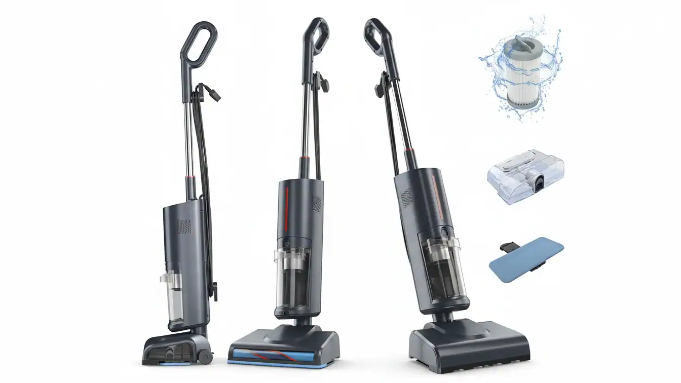
Tear-Down (Wiring)
A technical teardown verifies that internal wiring meets 2026 safety requirements, such as using 12 AWG copper for power circuits and 90°C-rated insulation. Inspectors check for UL-listed non-reversible crimps and dedicated grounding conductors to ensure long-term reliability in high-current devices like EV chargers and portable fridges.
Conductor Gauge and Insulation Integrity
Internal audits prioritize the verification of conductor sizing and insulation types to prevent thermal failure. Standards typically mandate 12 AWG copper THHN/THWN for branch power circuits, while control wiring requires at least 14 AWG stranded copper to provide necessary flexibility and vibration resistance. High-performance devices, such as compressor-driven portable fridges, must utilize insulation rated for 600V with a minimum 90°C dry-heat tolerance to resist degradation during continuous high-current operation.
Material restrictions also dictate the safety of specialized installations. Audits ensure that pure copper is used where aluminum is prohibited, particularly in underground or exterior site-lighting leads. For these applications, conductors must meet #8 AWG copper specifications with XHHW insulation and be housed in PVC conduits to protect against environmental stressors and moisture ingress.
Termination Standards and Grounding Continuity
The integrity of electrical terminations determines the overall reliability of the power system. Technical inspections confirm the use of non-reversible compression lugs installed with UL-listed, manufacturer-matched dies to eliminate the risk of arcing. During the teardown, auditors verify that all wire strands were wire-brushed before the crimping process and that the total number of crimps applied to each lug adheres strictly to the manufacturer’s technical data sheet.
Grounding systems must provide a continuous path to earth to protect against faults. Inspectors assess equipment-grounding conductors against NEC Article 250 for all circuits exceeding 50V, which may include 250 kcmil copper ground wires for medium-voltage infrastructure. For telecommunications components, bonding must comply with ANSI/TIA-607 standards, requiring #6 AWG copper and dual-hole compression lugs to maintain NEBS Level 3 reliability across racks and grounding bars.
“Golden Sample” Sealing
A golden sample serves as the finalized physical unit meeting all engineering requirements, including vacuum levels for car fridges and pressure tolerances for air pumps. We use this benchmark to calibrate 100% of production units against specific helium leak rates and material plating thicknesses verified in 2026 quality audits.
| Technical Metric | Requirement Threshold | Testing Standard |
|---|---|---|
| Helium Leak Rate | 10⁻¹¹ mbar × liter/sec | Mass Spectroscopy |
| Pressure Tolerance | Up to 140 MPa (20,000 psi) | ASME Section VIII |
| Gold Plating Thickness | 0.25 – 2.5 Microns | ASTM/MIL-STD |
| Thermal Conductivity | 330 kcal/m·h·°C | Gold Plating Benchmarks |
Certification of Physical Benchmark Samples
Engineers verify the housing material composition using ABS, PC, and TPU to meet IATF 16949 requirements. We physically seal the master unit to prevent environmental degradation, ensuring the sample maintains its aesthetic and functional integrity for 2026 factory audits. This preservation allows quality teams to compare mass-produced units against a stable physical reference.
The inspection process utilizes triple-layer protocols, including IQC, PQC, and FQC, to confirm the sample reflects the final OEM design. We store signed and dated samples in secure locations to resolve any future disputes regarding color matching or assembly finish. This documentation creates a clear chain of custody for quality expectations.
Quantitative Performance and Tolerance Mapping
Leakage testing relies on helium mass spectroscopy with sensitivity levels reaching 10⁻¹¹ mbar × liter/sec. These standards ensure airtight integrity for fridge compartments. We also validate plating thicknesses between 0.25 and 2.5 microns, which provides the necessary corrosion resistance for automotive components exposed to high humidity.
Pressure capacity testing for specialized air pump components reaches 140 MPa to prevent extrusion or seal failure under load. Gold-plated parts must achieve thermal conductivity benchmarks of 330 kcal/m·h·°C to manage heat dissipation in EV charging environments. These quantitative checks follow ASTM D1970 and MIL-STD guidelines to verify high-cycle fatigue resistance and load-deflection performance.
Final Thoughts
Rigorous evaluation transforms subjective observations into measurable data. Technical teams use specific metrics, ranging from suction pressure curves to wiring gauge audits, to eliminate guesswork during the sampling phase. Establishing clear rejection criteria for surface defects and seal compression protects the brand from expensive field failures and recalls.
Adhering to these engineering standards ensures that car accessories and home units perform reliably in real-world conditions. A vetted sample serves as a blueprint for the entire manufacturing cycle. This disciplined approach reduces production waste and keeps quality consistent from the first prototype to the final shipping container.
Frequently Asked Questions
What procedures ensure the quality of a vacuum cleaner prototype?
Quality assurance teams use ASTM D3078 bubble emission tests and ASTM F2338 vacuum decay measurements to verify seal integrity. These protocols involve submerged water testing where zero bubbles must appear at specific vacuum levels. Inspections follow ISO 2859 AQL sampling methods and require equipment calibration every six months to maintain accuracy through 2026.
How is the golden sample used during the evaluation process?
The golden sample acts as the validated reference point for all subsequent production batches. Technical teams compare mass-produced units against this master sample’s performance metrics, including suction power and motor noise levels. This process ensures every unit matches the approved technical specifications and global safety certifications established during initial prototyping.

 English
  Español
  Français
  Deutsch
  Português do Brasil
  Русский
  한국어
한국어  日本語
日本語  العربية