 跳转到主要内容 跳转到页脚

Industrial engineering teams often face a choice between the tactile reliability of manual dials and the automated efficiency of self-adjusting heads. Selecting the right height adjustment tech determines whether a system maintains precision under load or succumbs to mechanical drift. As production requirements become more demanding, the trade-off between manual control and sensor-driven automation impacts both maintenance schedules and overall assembly accuracy.
We compare these two approaches by looking at performance metrics like the 0.003mm repeatability offered by manual systems and the 0.00077-inch increments achieved through vernier threads. This analysis covers durability benchmarks including 5,000-cycle endurance testing under 100 kg loads and compliance with automotive vibration standards. By examining cost structures and mechanical failure modes, we provide the data needed to integrate the most stable elevation mechanics into your workflow.
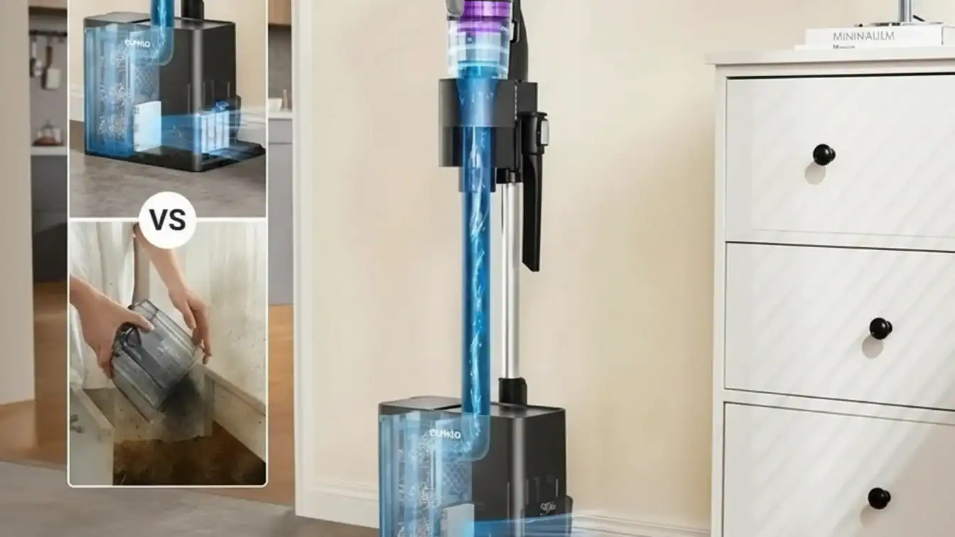
The Necessity of “Lifting the Nose” on High Pile
Lifting the nose provides critical two-axis vertical movement for aligning passenger boarding bridges with aircraft categories C through E on elevated stands. This mechanism utilizes hydraulic chucks and balance plates to ensure stability, preventing overturning while using 480V three-phase power systems to maintain reliable actuation under dynamic loads.
Vertical Elevation Mechanics for Aircraft Alignment
The elevation system enables precise vertical and horizontal movement on two axes to accommodate aircraft categories C through E. High-pile airport stands often present significant height differentials that require specialized tunnel elevation to ensure the bridge floor remains level with the aircraft door. Engineers utilize hot-dip galvanized steel panels and automated spot-welding to construct these tunnels, providing the corrosion resistance and structural integrity necessary for a long service life in harsh tarmac environments.
Operating these elevation systems reliably depends on meeting specific electrical requirements. The 2026 standards require 480V ±10% three-phase power at 60 Hz to support consistent elevation cycles without motor fatigue. This high-voltage configuration delivers the necessary torque for vertical movement under full load, ensuring that the noseloader remains stable and responsive during the critical docking phase of aircraft handling.
Hydraulic Stability and Safety Load Requirements
Hydraulic extensions insert into the upper inner diameter of the pile to maintain a secure grip via pressing rubber plates. This mechanism uses a chucking cylinder to apply radial pressure, creating a high-friction connection that prevents vertical slippage during the lift. By engaging the inner wall of the pile, the hydraulic system minimizes the risk of structural deformation and provides a more stable anchor point than external clamping methods.
Balance plates and cables provide horizontal stability, replacing less secure wire noose methods to prevent overturning during hoists. This engineering approach centers the load and reduces swaying when the crane positions the pile. Safety protocols for vibratory hammers further mandate that the total load remains under 50% of the crane’s rated capacity. This limitation manages vibration intensity and protects the crane’s boom and hydraulic systems from the dynamic stresses associated with high-pile driving operations.
Manual Dials: The Pro’s Choice for Precision
Professional technicians in 2026 rely on manual dials for their mechanical stability and tactile feedback. These systems eliminate electronic drift and offer repeatability as tight as 0.003mm. By using analog counters and fine-adjust screws, pros achieve high accuracy without the software lag or battery dependency found in digital alternatives.
| Technical Feature | Specification | Industrial Advantage |
|---|---|---|
| Repeatability | 0.003mm | Ensures consistency in high-tolerance mold and jig production. |
| Fine Adjustment Range | 10mm | Provides granular control for sub-millimeter positioning. |
| Stem Compatibility | 6mm / 8mm | Standard mounts fit a wide variety of industrial indicators. |
| Measurement Force | 0.5N to 3N | Prevents surface deformation on delicate workpieces. |
Mechanical Stability and Direct Reading Interfaces
Analog one-rev designs provide continuous visual feedback that avoids the display jumping common in digital sensors. This mechanical interface allows technicians to monitor movement in real-time without processing delays. Manual systems utilize 8mm or 6mm stem mounts, ensuring they remain compatible with standard industrial height gauge indicators. This universal fit simplifies the integration of specialized dial indicators into existing workflows.
Mechanical up/down counters enable error-free tracking throughout the entire 300mm or 600mm stroke. By using physical gears and counters, the system maintains a reliable zero-point and avoids the electronic interference that can affect sensitive sensors in workshop environments. This direct reading capability allows for quick, intuitive adjustments during complex inspection tasks.
Technical Tolerances and Contact Force Management
Fine adjustment feed screws offer a 10mm range of travel for exact positioning with a 0.001″ resolution. This level of mechanical control allows users to zero the instrument precisely against a workpiece or master block. Hardened and lapped surfaces on the base maintain flatness and ensure perpendicularity to 5μm. These material choices prevent wear and keep the instrument stable over thousands of measurement cycles.
Measurement forces are kept between 0.5N and 3N to protect the integrity of the surface being measured. Low contact force is essential for avoiding deformation on softer materials or thin-walled components. By managing these physical forces effectively, the gauge maintains a 0.003mm repeatability standard, which is critical for verifying the accuracy of precision molds and tooling.
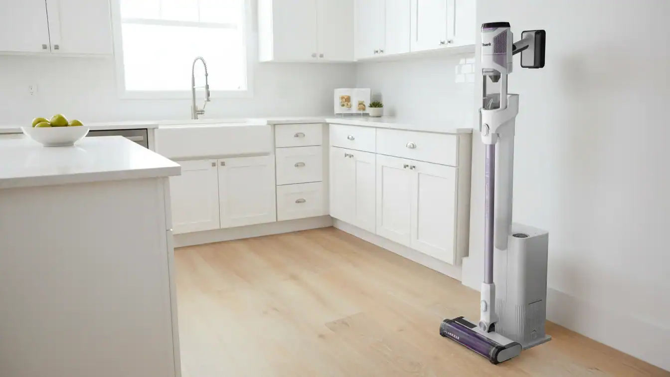
Self-Adjusting Heads: The Convenience Trade-off
Self-adjusting heads automate positioning through specialized vernier threads or motorized feedback loops, removing the need for manual calibration. While these systems provide precision increments as fine as 0.00077 inches, they involve complex components like dual tubular members and sensors that increase production costs and potential points of failure.
| Adjustment Type | Mechanical Configuration | Precision/Range |
|---|---|---|
| Fine Vernier | 14RH/20RH Thread Pitch Ratio | 0.00077″ Increments |
| Coarse Turnbuckle | 20RH/20LH Thread Style | High-Speed Positioning |
| Total Linear Range | Dual Tubular Members | ±0.100″ Range |
Vernier Mechanics and Micron-Level Precision
Mechanical self-adjustment relies on dual tubular members with unequal thread pitches to achieve high stability. By utilizing a 14RH/20RH ratio, the system creates lockable increments of 0.00077 inches. This configuration allows for micron-level linear positioning that manual systems struggle to replicate without extensive downtime for calibration.
The hardware uses self-locking features to maintain settings during high-vibration operations. Precision balls and conical lead-in ramps provide uniform radial expansion of the slotted ends, ensuring the assembly remains secure without external actuators. Internal splines and spring-loaded locking skirts maintain perfect alignment during high-cycle operations, though this complexity requires more time during initial assembly compared to standard threaded rods.
Automated Feedback Systems and Integration Costs
Motor-driven variants replace manual vernier adjustment with electronic feedback loops. These systems use a controller to process signals from strap tension or pressure sensors, which then drives a gear rack to reach specific thresholds. This automation eliminates human error in tightening and ensures consistent pressure across different operational cycles.
The shift to electronic automation introduces significant integration costs. Spool assemblies, gear trains, and feedback sensors require robust shielding to survive harsh environments, particularly in automotive manufacturing. KelyLands R&D teams focus on balancing these smart digital controls with mechanical durability, ensuring that automated components meet the rigorous demands of ISO 9001:2026 standards while maintaining long-term repeatability.
Scale Your Brand with Premium OEM/ODM Vacuum Cleaners

Mechanism Durability: Testing Detents for 5000 Cycles
Testing detents for 5,000 cycles ensures adjustment mechanisms remain safe and functional throughout their lifespan. By applying a 100 kg load during repetitive operation, we identify potential failure modes like deformation or stiffness. This standard validates that the hardware maintains its structural integrity and performance under heavy use in 2026.
Core Standards for Mechanical Endurance Testing
Testing teams rely on the EN 1725:2023 standard to validate the strength and long-term durability of adjustment hardware. During these procedures, a 100 kg test dummy simulates real-world user weights up to 110 kg while the mechanism operates through repetitive motions. The hardware must complete 5,000 full cycles without showing structural failure or losing its primary function. This process reveals common mechanical failure modes, including detent wear, material deformation, and component fatigue, ensuring the product remains reliable over years of daily use.
Quantitative Metrics and Dynamic Wear Inspection Protocols
Technical assessments employ Real-time Wear Testing (RWT) and Accelerated Wear Testing (AWT) to track component degradation. Technicians monitor pressure waveforms to verify that mechanisms attain target pressures for at least 5% of every individual cycle. Detailed inspections at 5,000-cycle intervals provide precise measurements of mechanical stiffness and help detect developing structural looseness. High-speed video analysis documents kinematics and hydrodynamic performance, providing a visual record of potential failure points that standard observation might miss.

The “Rattle” Test: Ensuring Stability at Max Height
The rattle test uses electrodynamic shakers to apply sine and shock forces to components at their maximum height. By simulating road vibrations up to 150Hz and maintaining noise levels below 2.5 sones, engineers identify structural weaknesses and loose-fit issues, ensuring the product remains quiet and stable under 2026 automotive standards like GMW14011.
Root-Cause Analysis via Multi-Axis Vibration
Engineers apply multi-axis sequential excitation—encompassing vertical, fore-aft, and lateral directions—to isolate specific failure modes in telescopic car accessory frames. This testing methodology focuses on the maximum lever arm extension, where components experience the highest risk of structural resonance. By simulating real-world dynamic loads at these extreme positions, the process identifies vulnerabilities that single-axis tests typically miss.
Squeak & Rattle (S&R) systems utilize a frequency range from 0.5Hz to 150Hz to mimic specific road surface profiles. These electrodynamic setups provide precise control over displacement and acceleration, allowing for the diagnosis of rattles in height-adjustable mechanisms without the interference of hydraulic noise. This precision ensures that mounting tables and internal guides maintain structural integrity during intense vibration cycles.
Vibration Metrics and Regulatory Benchmarks
Validation requires reaching strict velocity targets to simulate harsh driving conditions. Testing protocols mandate maximum velocities of 94 in/s for sine forces and 137 in/s for shock forces. These metrics, combined with a maximum displacement of 4.0 inches peak-to-peak, confirm that the component can withstand chuckhole transients and sudden impacts without mechanical failure or excessive movement.
Compliance with 2026 industry standards, including GMW14011, BMW PR311.2, and Ford CETP-01.10-L-413, hinges on maintaining operational noise below 2.5 sones N10 within semi-anechoic chambers. Monitoring these levels helps detect Buzz, Squeak, and Rattle (BSR) aging signs early in the development cycle. High-force actuators delivering over 10kN of peak force test payloads up to 350kg, ensuring stability across a temperature range of -40°C to +65°C.
Final Thoughts
Choosing between manual and auto systems requires balancing the need for speed against long-term mechanical reliability. Manual dials provide a dependable, cost-effective solution for high-tolerance work where electronic interference or surface softness might compromise a sensor. Motorized heads simplify operation by automating the calibration process, yet they introduce complexity that raises the price point and increases potential maintenance requirements.
Strict testing protocols like EN 1725:2023 and GMW14011 ensure these mechanisms withstand years of heavy use. Engineers run components through 5,000 cycles under 100 kg loads to reveal material fatigue before products reach the workshop or tarmac. As the industry adopts 2026 standards, the focus remains on reducing noise and vibration through multi-axis testing, ensuring that both manual and automated systems stay stable at their maximum extension.
Frequently Asked Questions
Does manual height adjustment increase the bill of materials cost significantly?
Manual height adjustment utilizes basic pneumatic cylinders that add roughly $10 to $20 to the bill of materials (BOM). This allows manufacturers to keep product costs within the $100 to $200 range. Automated systems add a much higher premium of $50 to $150 because they require integrated motors and sensors.
Is auto-adjustment technology effective on ultra-soft or high-pile carpet?
Auto-adjust systems often fail on ultra-soft carpeting because the surface lacks the traction required for accurate weight-sensing. In 2026, most user guides recommend switching to a manual override when operating on high-pile surfaces to prevent the mechanism from defaulting to incorrect heights.
What is the maximum clearance height provided by these mechanisms?
Standard height-adjustment mechanisms offer a maximum clearance of 22 inches. This aligns with the common industry range of 16 to 22 inches measured from the floor to the base of the unit.

 English
  Español
  Français
  Deutsch
  Português do Brasil
  Русский
  한국어
한국어  日本語
日本語  العربية